|
|||||||


| Sponsored Links (Register now to hide all advertisements) |
|
|
 |

|
Thread Tools | Display Modes |
 02-19-2012, 12:30 AM
|
#41 |
|
Senior Member

Join Date: May 2010
Location: Suttons Bay, Mich.
Posts: 3,384
|
I really commend you guys that work on mostly wood framed cars, this looks exhausting!! Great work.
__________________
Respecting and Resurrecting Ford Model A's. |

|

|
|
02-21-2012, 02:15 PM
|
#42 |
|
Senior Member

Join Date: Jul 2010
Location: Queen Creek AZ
Posts: 519
|
Nice build I will keep my eyes open as I am doing the same deal on my car
Frenchy |
|
|
|
| Sponsored Links (Register now to hide all advertisements) |
|
|
|
07-12-2012, 02:12 AM
|
#43 |
|
Senior Member
Join Date: Jul 2010
Location: Queen Creek AZ
Posts: 519
|
Any updates on your project ?
Frenchy |
|
|
|
|
07-12-2012, 04:08 PM
|
#44 |
|
Senior Member
Join Date: Feb 2011
Location: NNNNNNNNJJJJJJJJJJ
Posts: 6,790
|
Russ, thank you for those last photos. I am missing the upper triangles and cable/turnbuckles and was wondering how I was going to adjust the doors to the posts. Those photos are worth a million....
|
|
|
|
|
07-14-2012, 12:27 AM
|
#45 |
|
Senior Member
Join Date: Aug 2011
Location: Millbrae, CA
Posts: 504
|
a little update on my cabriolet body assembly.
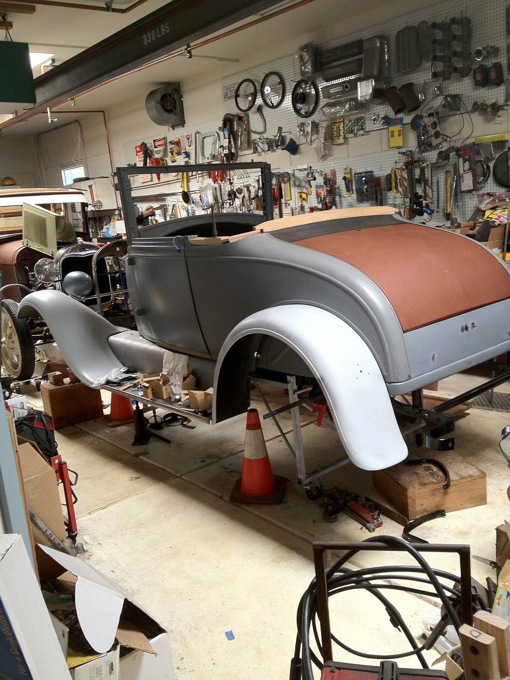 From the photo, it looks a little bit like there has been more progress than actual. I have made progress; but very little has been permanently assembled as fits are not as good as they should be yet. My right sill had a downward warp at the rear which required planing the bottom side back to flat, notching the upper side, laminating a thicker piece in place and trimming/planing it back to shape. I am still putting things together, looking, measuring, taking apart, adjusting, and reassembling. With my most recent assembly I got so far as to set in the package tray and seat back, and do some door fit adjustments. 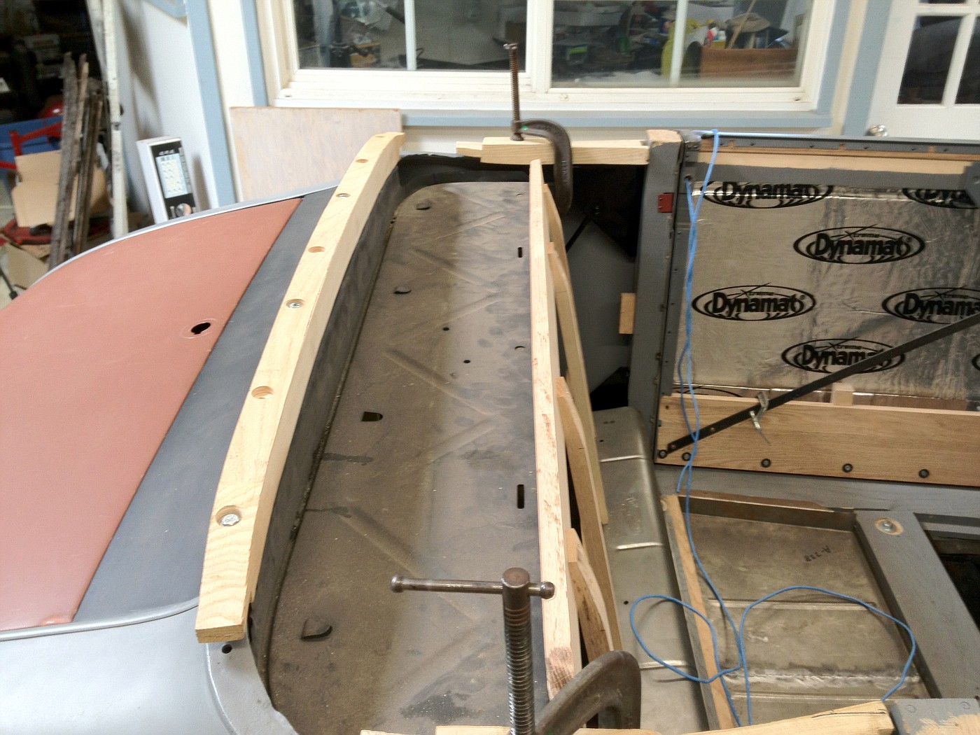 The doors are assembled to the point of having most of the wood in. I also have worked on the cowl to door gaps, getting a fairly even approximate 1/8 gap, which should be OK for paint clearance. Eystein recently posted a drawing of the 68B main sill rail and I realized some of my fit issues could be explained by my rails not having the raised area under the rumble seat pan and to the rear, as shown in the posted drawing. I laminated additional wood to the top rear of my sills and found that made a big improvement in some fits.  I am now getting close to good quarter panel to top of B pillar fits. Once they are good and other fit issues are corrected, I hope to nail on the quarter panels and start fitting the belt rail wood and triple hinges. 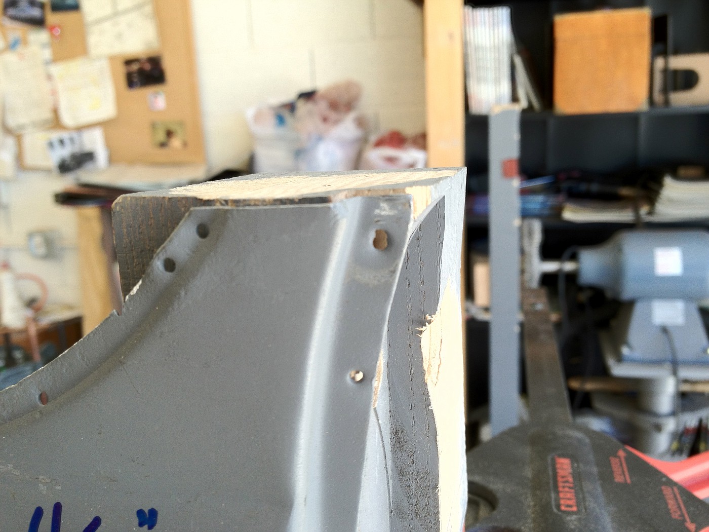 Oh, I took a quarter inch width out of my reproduction sheet metal fixed seat floor pan. It was pushing the main sill rails out too far, affecting door closing and fit of the sheet metal below the door where if meets the cowl. 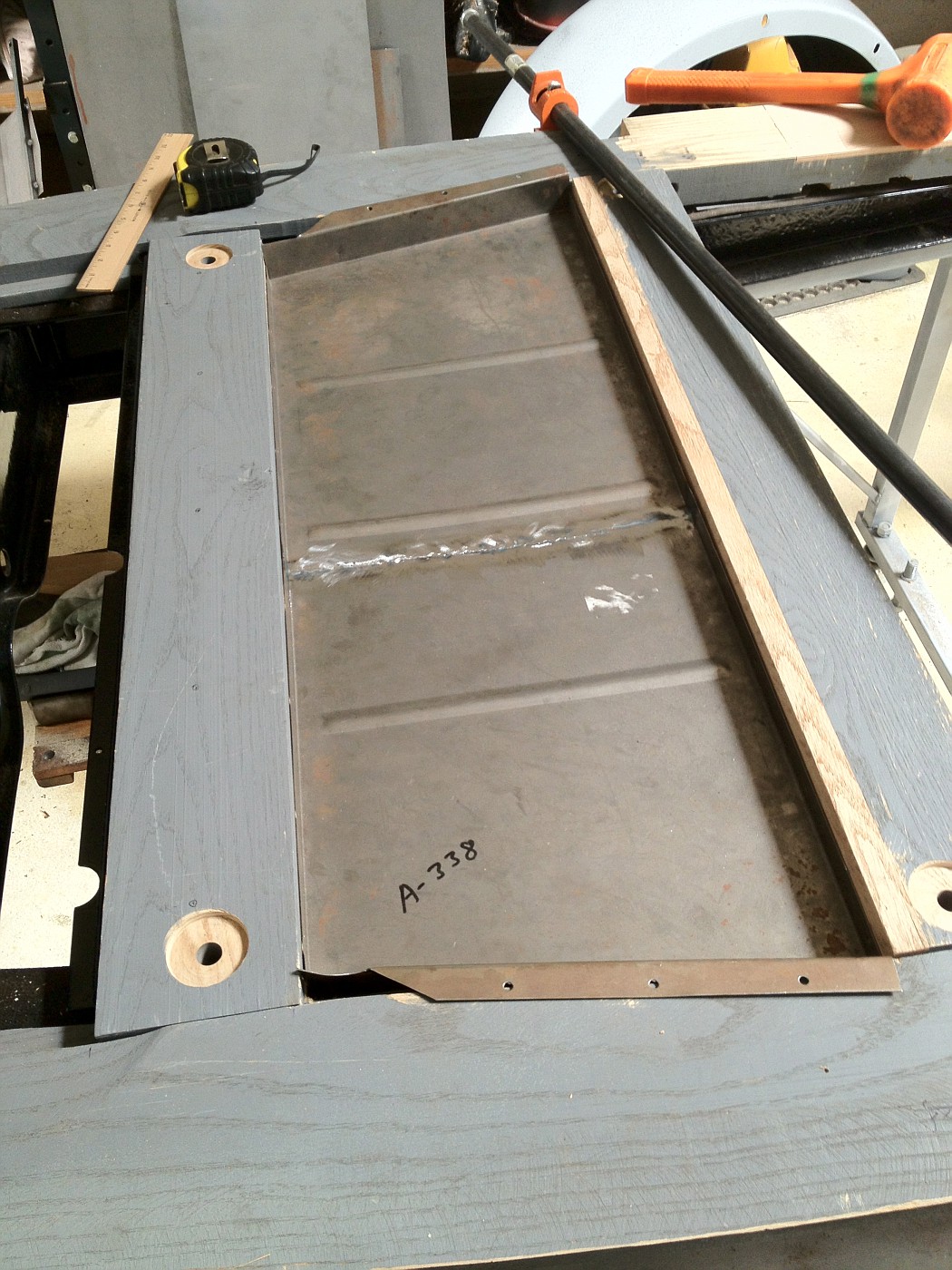 So I am still making a lot of adjustments and getting closer to real assembly. One of the things affecting my speed is that patch panels were installed on disassembled body panels nearly 20 years ago and each 1/8 misfit here and there needs to be identified and verified before I make final assembly/fit decisions on each fit issue. Thus many partial assemblies, tweaks, and reassembly. 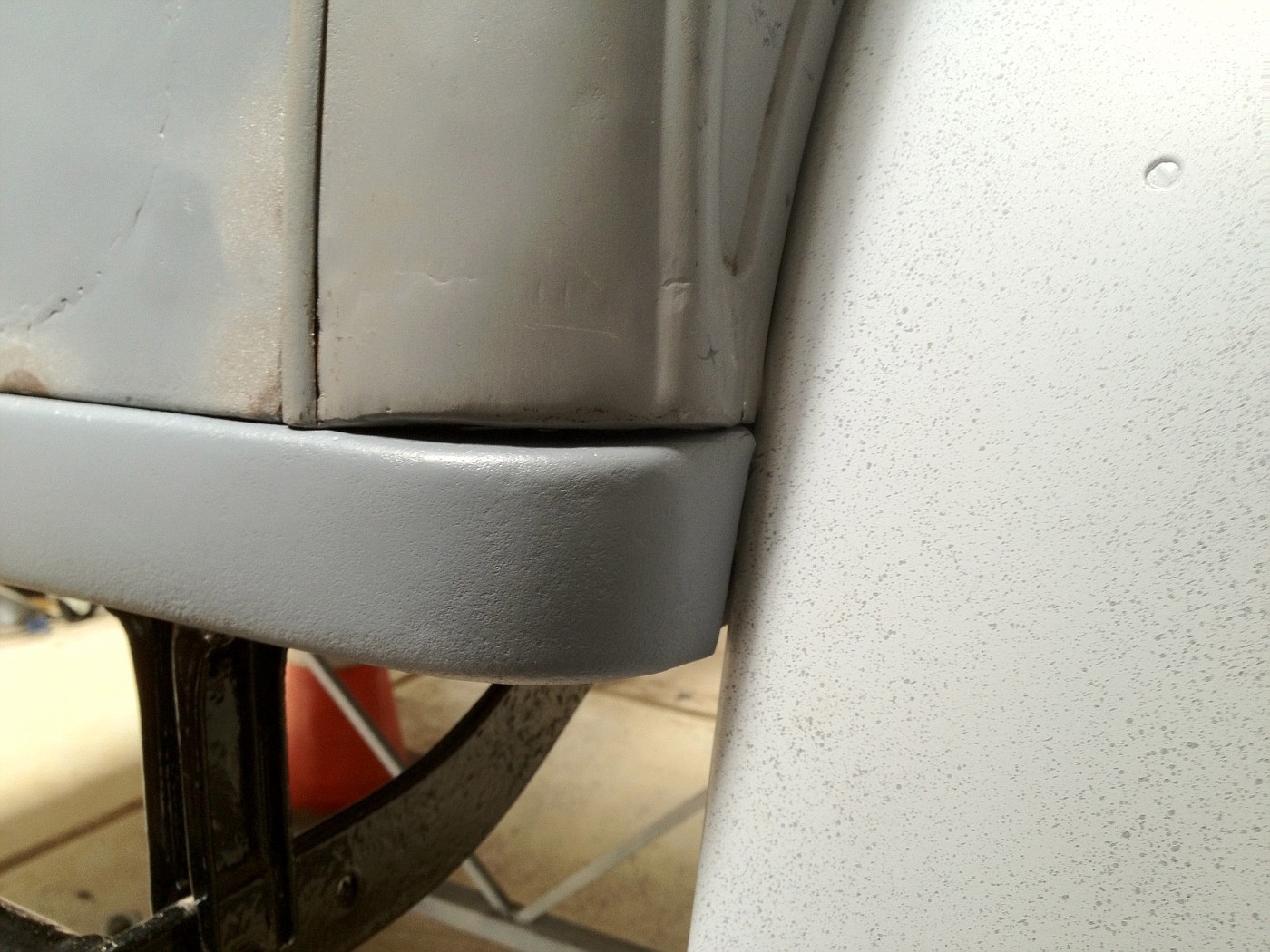 back gap of right rear quarter panel, not yet corrected Quarter panel to fender gap before: 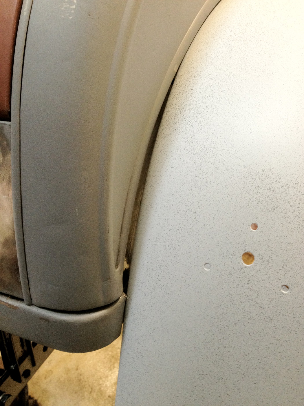 Quarter panel to fender gap after tweaking of the quarter panel: 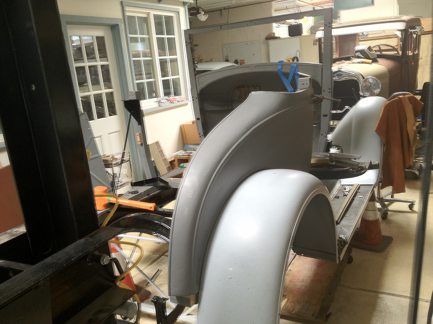 ...but it is all fun and I am making progress. |
|
|
|
|
07-14-2012, 12:54 AM
|
#46 | |
|
Senior Member
Join Date: Aug 2011
Location: Millbrae, CA
Posts: 504
|
Sponsored Links (Register now to hide all advertisements)
Quote:
I am glad the photos have helped. The triangle pieces should be easy to make and the turnbuckle assembly with a little 'blacksmithing' of the rod ends. I have seen open turnbuckles in some 68B cabriolet assembly photos. I can pull some dimensions off my pieces if it would help. I had to do some patching of my triangle pieces and made a false rivet head on one side where the original rivet head had been almost ground off. The screw hole location to the B pillar is not critical, but on the upper flange the holes will line up with the triple hinge, and attach with 1/4," iirc, bolts, or maybe #12. I am not that far along yet. Russ |
|
|
|
|

|
07-14-2012, 01:26 PM
|
#47 |
|
Senior Member

Join Date: May 2010
Posts: 3,099
|
Russ,
I'm pretty certain the vertical boards on the seat back wood should be reversed so the angled tops face the rear and the top plank becomes vertical. I believe it's the same as '28-29 Coupes so it should be easy to confirm. As far as your door gaps, If you have a true 1/8" it will appear excessive when finished. I have a 1" wide strip of cardboard measuring about .080" thick. It's actually a panel board scrap from making interior trim panels. On my original Briggs Fordor I can slip it into the hinge pillar gaps in MOST places. On my Roadster the gaps are about .010" less. There should be no measurable paint build in those areas.
__________________
http://www.abarnyard.com/ |
|
|
|
|
07-15-2012, 09:49 PM
|
#48 | |
|
Senior Member
Join Date: Aug 2011
Location: Millbrae, CA
Posts: 504
|
Quote:
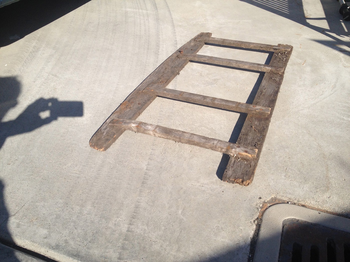
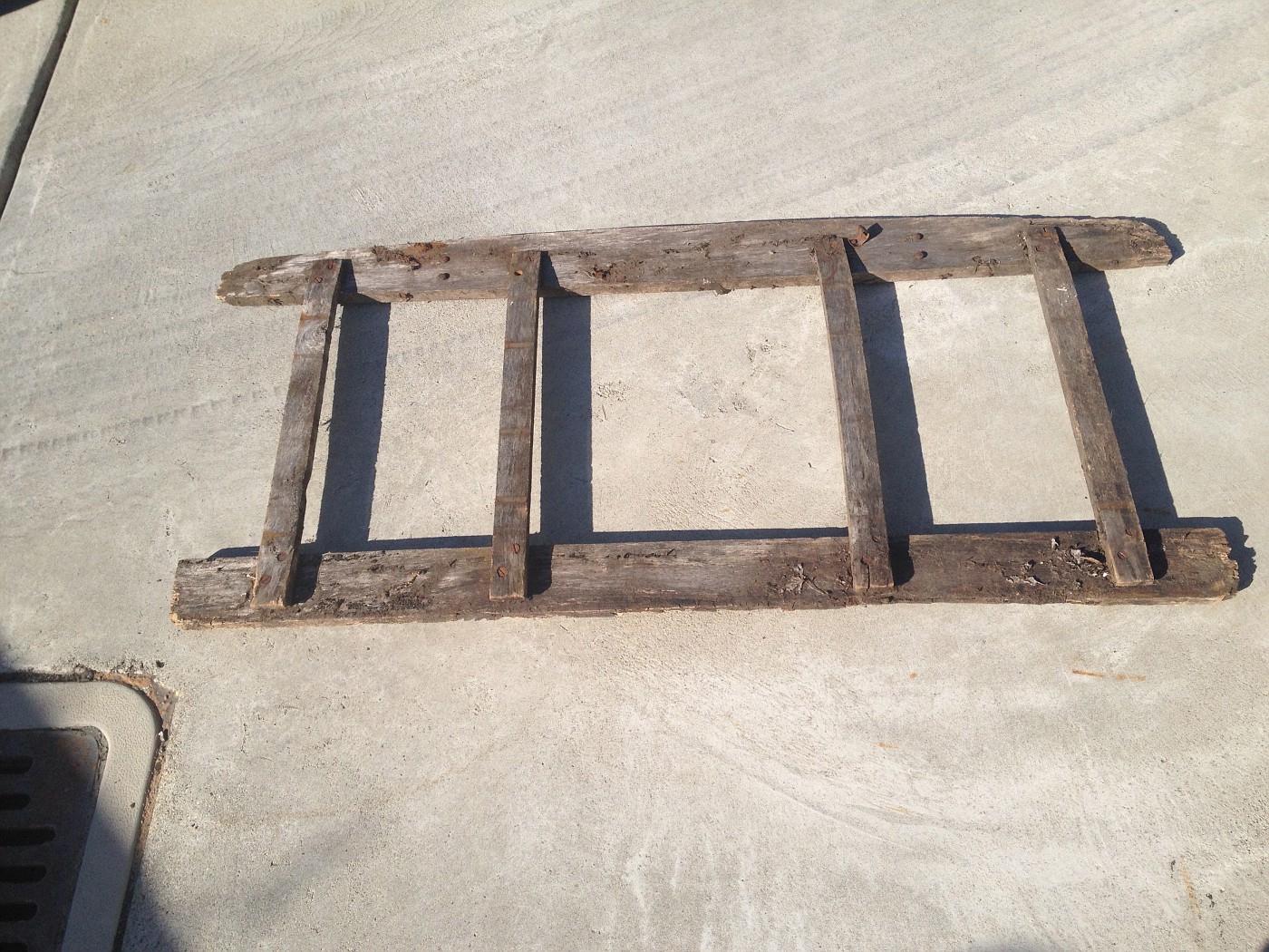
Regarding door gaps, I will shoot for 0.080 or less as I refine the door gap adjustment. I started with 3/8 on the left door gap and 0 to 1/8 on the right door to cowl gap. I am close to 1/8 now on both sides but still not at a perfect setting top to bottom. I took a few photos today of my original seat back. Maybe they will spark more discussion. I placed the seat back I fabricated with the top board to the very back as the original had all the upholstery nails on the back side. The other side with the vertical stringers forward had originally mounted the springs. the top edge of the top piece also had a round-over edge and a slight recess. Also note the vertical stringers each have a small notch that appears to be for holding the bottom of the seat back on the foldover back edge of the metal fixed seat riser.  My original seat back wood frame, not usable, but good as a pattern. 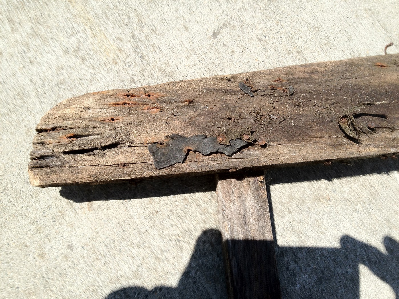 The slight recess at the top is barely visible, but is of uniform width across the top board, maybe 3/4", iirc. 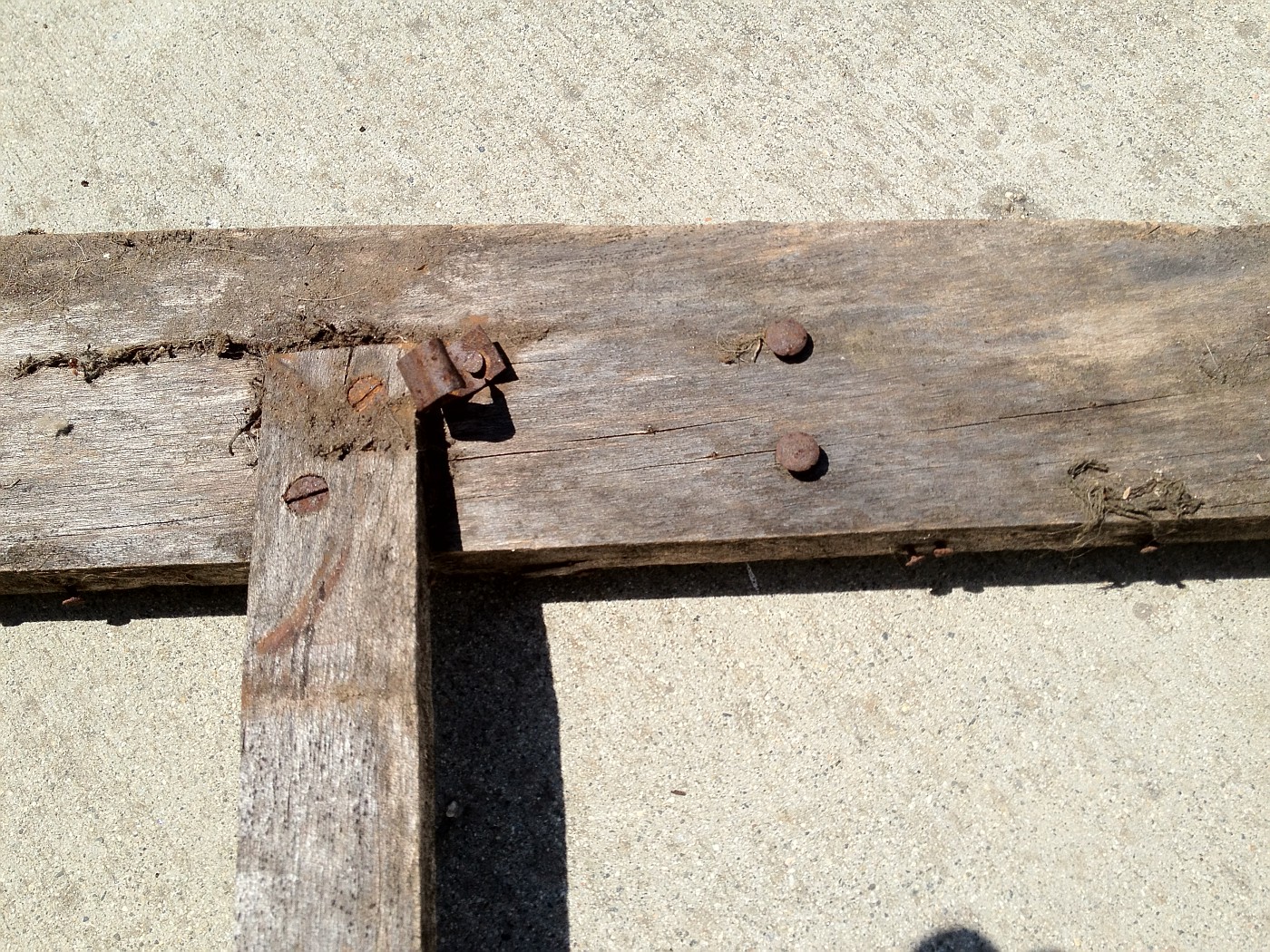 Note angle of vertical stringer and spring mounting bracket. The screws are countersunk and set the fit of the vertical boards in relation to the horizontal top and bottom. 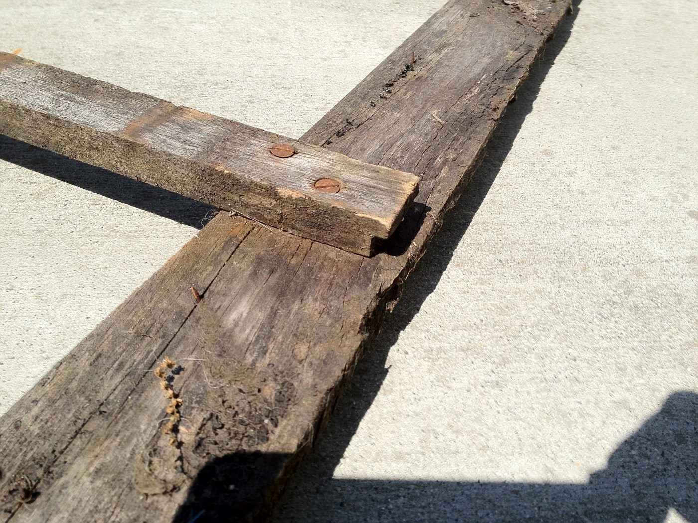 Note notch at bottom of stringer. This was typical for all. The frame construction was done as was my original. Does my placement of the seat back frame look proper when comparing to the photos of the original? Before I left it that way for progress photos, I tried it both directions and it seemed to fit best as I placed it. |
|
|
|
|
|
07-15-2012, 10:12 PM
|
#49 |
|
Senior Member

Join Date: May 2010
Location: South Florida
Posts: 14,054
 |
These types of threads are my favorite!!!
__________________
What's right about America is that although we have a mess of problems, we have great capacity - intellect and resources - to do some thing about them. - Henry Ford II |
|
|
|
|
07-15-2012, 10:58 PM
|
#50 |
|
Senior Member
Join Date: May 2010
Location: Ogden Utah
Posts: 242
|
When I restored my 68B back in the early eightys I started rith the radiator and shell mounted with the proper rubber shims. I then located my cowl and matehed it up for a perfect fit with the hood. I then attached the doors to the cowl which showed me the exact placement of the door posts for a perfect fit. It all came together very nice and was a blue ribbon winner in the national in San Diago
|
|
|
|
|
07-16-2012, 05:07 AM
|
#51 |
|
Senior Member

Join Date: May 2010
Posts: 130
|
"Regarding door gaps, I will shoot for 0.080 or less as I refine the door gap adjustment."
Russ, When you are checking the door gaps be sure to have the female dovetail in place. When I was messing with the gaps, if the gap got too small then the dovetail wanted to hit the door first. Also, it seems to me that my door gaps change slightly with the weather so I set my gaps towards .100 And finally, if you are using original top irons, locking them into place also determines final door gap because the top irons will put tension towards the rear forcing the gap open if everything was not set properly to begin with. |
|
|
|
|
07-16-2012, 11:28 AM
|
#52 | |
|
Senior Member
Join Date: Aug 2011
Location: Millbrae, CA
Posts: 504
|
Quote:
|
|
|
|
|
|
07-16-2012, 04:14 PM
|
#53 | |
|
Senior Member
Join Date: May 2010
Posts: 3,099
|
Quote:
Do you have the steel "hooks" that were riveted to the upper plank?
__________________
http://www.abarnyard.com/ |
|
|
|
|
|
07-16-2012, 06:41 PM
|
#54 | |
|
Senior Member
Join Date: Aug 2011
Location: Millbrae, CA
Posts: 504
|
Quote:
On the upper plank, there are two pairs of rivets, one pair can be seen on the third photo of my earlier post(9:49 pm 7/15). There have never been any hooks as long as I have had the car. The seat back was always problematic when I was driving the car in the early 1960's. More than once I recall the seat back slipped out of position if I hit too much of a bump. I have two mortised slots in the wood bar that supports the front of the package tray, and matching slots in the package tray. These line up with the two pairs of rivets on the upper plank of the seat frame. Possibly an offset strap or hook of some sort could have been used to hold the seat back in place. Until now I had never given those slots much thought. That wood bar is the only wood in the car that has had minimal damage and that I plan to use. That wood package tray support bar is held by a bolt on each end attached to the belt rail wood. I recall other cabriolet photos I have seen seem to show the package tray supported by a strap screwed to the belt rail like my 45A's package tray. My package tray has no provision for such a strap. |
|
|
|
|
|
07-22-2012, 02:35 PM
|
#55 |
|
Senior Member
Join Date: May 2010
Posts: 332
|
Could you post a full photo of the other side of your original seat back ? Thanks , Norm
|
|
|
|
|
07-22-2012, 10:07 PM
|
#56 | |
|
Senior Member
Join Date: Aug 2011
Location: Millbrae, CA
Posts: 504
|
Quote:
|
|
|
|
|
|
07-24-2012, 03:42 PM
|
#57 |
|
Senior Member
Join Date: May 2010
Posts: 332
|
Thanks a lot. That is what I was looking for
|
|
|
|
|
04-29-2014, 11:05 PM
|
#58 |
|
Senior Member

Join Date: Apr 2013
Location: Big pine Ca 93513
Posts: 797
|
I have an original 68c body in good shape if anyone needs photos measurements of sub-frame , etc. Spencer , big pine
|
|
|
|
|
04-30-2014, 07:40 AM
|
#59 |
|
Senior Member
Join Date: May 2010
Location: South East NJ
Posts: 3,398
|
FWIW, All the lower rear panels should have the hole in them for the rear spare.
If you are doing side mounts it should have a plug in the hole. I believe the plug should be painted body color. Before you go too far with the rumble lid. Put the latch in it. The latch must fit snug to the underside of the sheet metal. The is controlled by the two screws on the face. My repro was positioned too far away from the sheet metal and caused the lid to stick up at the front edge. I welded up the holes and moved them. You will expect to need to change the height of the two braces that go under the upper cross panel. These braces will alter the in-out position of the top of the door posts. The affects the door top to bottom in-out fit. You would be wise to screw your quarter panels on to the wood tightly. Clamping the quarters in place is a mistake I made and found things did not go so good when I started tightly putting the body together. I suggest you start fitting your top parts now too. It all has to work together. I will continue to warn you that Cubel does not do his wood properly. Refer to any original wood and be sure what you see makes sense. |
|
|
|
|
04-30-2014, 08:23 AM
|
#60 |
|
Senior Member

Join Date: Oct 2013
Location: Lopez Island, Wa.
Posts: 276
|
Boy do I love the pictures, wish I could do that..one thing I saw was why was seat pan edges angled?? mine dropped in flush side to side...one thought, I think because the B piller bolts clear through the sub rail it must be in place first?? very critical to door fitting later, then wrap sheet metal around the piller and nail.. I have lots of pictures of my early 29 cabby going together but cannot make pictures work on this site...would email to anyone if they let me know their email address..
__________________
The only thing worth learning is what you learn after you know it all !! ")
|
|
|
|
|
«
Previous Thread
|
Next Thread
»
 Linear Mode

|
|

| Sponsored Links (Register now to hide all advertisements) |
|
|
All times are GMT -5. The time now is 01:26 PM.