|
|||||||


| Sponsored Links (Register now to hide all advertisements) |
|
|
 |

|
Thread Tools | Display Modes |
 06-24-2011, 05:23 AM
|
#21 | |
|
Senior Member

Join Date: May 2010
Location: Eastern Tennessee
Posts: 11,519
|
Quote:
. |
|

|

|

 )
)|
06-24-2011, 09:56 AM
|
#22 |
|
Senior Member

Join Date: May 2010
Posts: 361
|
I can see in the shape of the Crazydaddio chamber pic some other characteristics that, to my thinking, would make it very effective. The radius around the perimeter of the valve area and transfer area would make for smooth and effiecent flow to and from the valves with minimal turbulence and ricocheting around of the gasses, as turbulence during intake and exh phases would be detrimental to cylinder filling and"'chamber emptying". The large radius at the end of the transfer area would direct the intake charge about as efficiently down into the cylinder as possible, but during compression would make terrific beneficial turbulence , as already stated. My confusion has to do with getting the explosion onto the top of the piston, and at tdc, most of the top of the piston is not exposed. But I think I am starting to understand what really happens. If the expanding "ball of flame" takes say .0025 of a second to reach full pressure from the moment of spark, by that time the downward stroke has begun, the "pressure ball" can reach the whole top surface of the piston, and that will occur at the most advantageous crank angle (depending on RPM and ign timing) to use the pressure during its availability. I guess most of you already knew that, or am I correct in my thinking? Again, BMEP, dyno testing and track performance (which includes flexibility and longevity) are the real proof of concept. I have a Lion Speed single plug head and dual plug head and though I don't understand their chamber technology, their dyno results are impressive for power and RPM range. That is not to denigrate by comparison anyone else's head, as there are some impressive and consistent reports on many FH's and all are interesting. I hope more of you will relinquish your FH chamber design secrets or ideas on this thread so we can go faster, impress ourselves and maybe blow up another engine or two.
|
|
|
|
| Sponsored Links (Register now to hide all advertisements) |
|
|
|
06-24-2011, 10:44 AM
|
#23 | |
|
Senior Member

Join Date: May 2010
Location: Orange, Ca.
Posts: 197
|
Quote:
Careful, talk of speed and performance modifications on this site may lead to severe tongue lashings, banishment to far away lands, and/or burning at the stake. The quest for speed is considered "witchcraft" on here sometimes. ")   I only showed the B.S. head as an example of how different it is then the typical A/B HC head. Brent should show us what a "real" JR Dragster head looks like. Lets not get off topic with the debate over how alcohol is used in racing. There are schools of thought that believe the squish area between the top of the piston and the head is beneficial to the combustion process. The thought is that the more piston area that comes as close as possible to the head, the better the heat transfer and the cooler the combustion. Without cool oil squirting onto the bottom of the piston, there is not efficient way to cool the piston. This area will also create detonation too. So the size, clearance, and shape of the squish is important. It is this reason that if you are using a "crow's foot" style squish you want the spark plug near the intake valve which is the coolest part of the chamber. The squish will help flame propagation. . |
|
|
|
|
|
06-24-2011, 10:59 AM
|
#24 |
|
Member Emeritus
Join Date: May 2010
Location: Madison, NJ
Posts: 5,230
|
I was privy to a limited range of selected bits of secrets from the late great Flatdog, builder of probably the most powerful (12.9 in 3,000 pound '34) street driven flathead on the planet. Remember, canted valves and closer chamber, so not necessarily transferable to bangers...
One thing was that flow at back of valves was minimal...best approach was minor clearance behind valve, at least .030 above valve to allow the slight flow. Almost all serious flow was right out the cylinder side, across the back of the valve, and shape of the BOTTOM of the pocket was critical to encouraging this. He also said that flow bench showed that most flow was on the intake side of chamber because...startling observation, confirmed by other flowbench wizards...the EXHAUST flow mostly followed that side!! I suspect this was a big factor in his work on chamber roof. And I have seen elderly circle track engines with a block relief only on that side... Flatdog was a major presence in the flathead world, and regularly conversed by phone with various Bonneville types, all people with some sort of flow bench, some with dynos. They would very guardedly mention tiny fragments of theri secrets to each other, and try to gauge if the other guy had observed anything similar. High tech spy world...I think if I had ever walked into the garage at the wrong time and caught a glimpse of his total chamber design, he would have had to kill me. Low tech secrets: He started his flow work with a humungous shop vac, tossing kitty litter into the airstream! As things got more sophisticated, he learned from Elmo Rodge how to forn clear plastic shell copies of his chambers so he could put a transparent roof over the flow. |
|
|
|
|
06-24-2011, 11:20 AM
|
#25 |
|
Senior Member

Join Date: May 2010
Posts: 397
|
my practical comment on the Winfield "Crows Foot" design, no dyno figures, no theory.
|
|
|
|
|
06-24-2011, 11:37 AM
|
#26 | |
|
Senior Member

Join Date: May 2010
Location: Cincinnati, OH
Posts: 209
|
Sponsored Links (Register now to hide all advertisements)
Quote:
|
|
|
|
|
|
06-24-2011, 03:54 PM
|
#27 |
|
Senior Member
Join Date: May 2010
Location: Orange, Ca.
Posts: 197
|
Here are a couple of "old " banger HC chambers:
Weiand (7.6:1) 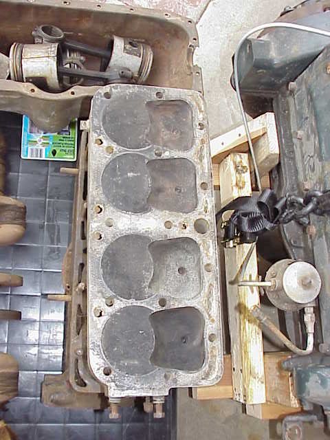 Late Winfield (7:1) Cyclone (8.25:1) Thomas 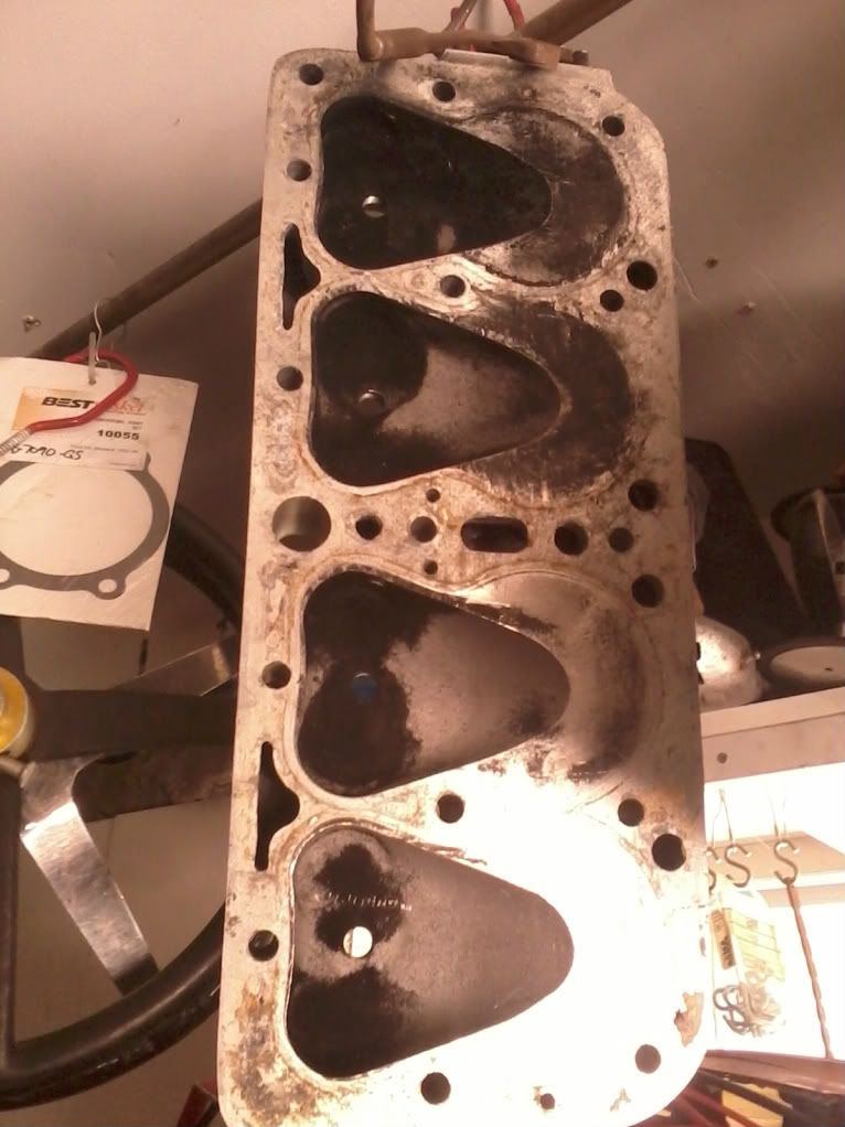 . . Last edited by Crazydaddyo; 06-25-2011 at 01:37 PM. |
|
|
|
|
06-25-2011, 04:09 PM
|
#28 |
|
Senior Member
Join Date: Jun 2011
Location: Upstate South Carolina
Posts: 794
|
Thanks for fixing the pics CDO...hate to see this one die, interesting to me as I am about to purchase a new head.
Still hoping Brent will show us the JR dragster head. |
|
|
|
|
06-25-2011, 07:32 PM
|
#29 | |
|
Senior Member
Join Date: May 2010
Location: Orange, Ca.
Posts: 197
|
Quote:
Here are some pictures of the Harley KR set up: |
|
|
|
|
|
06-26-2011, 11:08 AM
|
#30 |
|
Senior Member
Join Date: Jun 2011
Location: Upstate South Carolina
Posts: 794
|
Nice pics of the HD block, got any of the head?
|
|
|
|
|
06-26-2011, 12:18 PM
|
#31 |
|
Senior Member

Join Date: May 2010
Location: Southern Maine
Posts: 1,499
|
Barney Navarro made V8 heads that used some of these HD ideas. One of his last projects I think.
|
|
|
|
|
06-26-2011, 12:37 PM
|
#32 | |
|
Senior Member
Join Date: May 2010
Location: Orange, Ca.
Posts: 197
|
Quote:

|
|
|
|
|
|
06-26-2011, 02:05 PM
|
#33 |
|
Senior Member
Join Date: May 2010
Posts: 397
|
Mike hart had a chamber that looked like he working along the lines of the HD design. I have had 2 of the cast iron Winfield "Crows Foot" heads and both have had added clearance for larger valves. When I saw the first one I thought that a previous owner had modified that area but then the second one had the same exact cuts. The area between Valve chambers is .250 or less and requires a "B" gasket. Awhile back some one informed another poster that the "A" gasket worked on Winfield's. Looking at the photo of the Cyclone it might get by with an "A" but I'm sure the Wieand would require a "B" gasket. I had to use a "B" gasket on my repop " Crows foot" Although the chambers are no where as big as the original cast Iron. I once met a old time tracer that told me they (he?) always ran 1 7/8" intakes and the original "Crows Foot" by Winfield will
' clear that size. Once read somewhere that winfield was forced to drop the "Crows Foot" design because off a Ricardo patent infringement. Can't find the reference now. |
|
|
|
|
06-26-2011, 04:27 PM
|
#34 |
|
Senior Member
Join Date: Jun 2011
Location: Upstate South Carolina
Posts: 794
|
Thanks for all the pics....interesting looking at all the different ideas.
|
|
|
|
|
«
Previous Thread
|
Next Thread
»
 Linear Mode

|
|

| Sponsored Links (Register now to hide all advertisements) |
|
|
All times are GMT -5. The time now is 04:22 AM.