|
|||||||


| Sponsored Links (Register now to hide all advertisements) |
|
|
 |

|
Thread Tools | Display Modes |
 06-04-2015, 12:58 PM
|
#1 |
|
Senior Member

Join Date: Jul 2013
Location: Johnstown, PA.
Posts: 137
|
6 volt positive ground.
I have: Single throw double throw on-off-on toggle switch Double filament 6 volt cowl lights Led lights for rear bumper 6 volt flasher marked P, L and X Can somebody help me with a wiring diagram. |

|

|
|
06-04-2015, 10:45 PM
|
#2 |
|
Senior Member

Join Date: May 2010
Location: South Florida
Posts: 14,054
 |
I don't know if this will help. Just don't wire what you don't want.
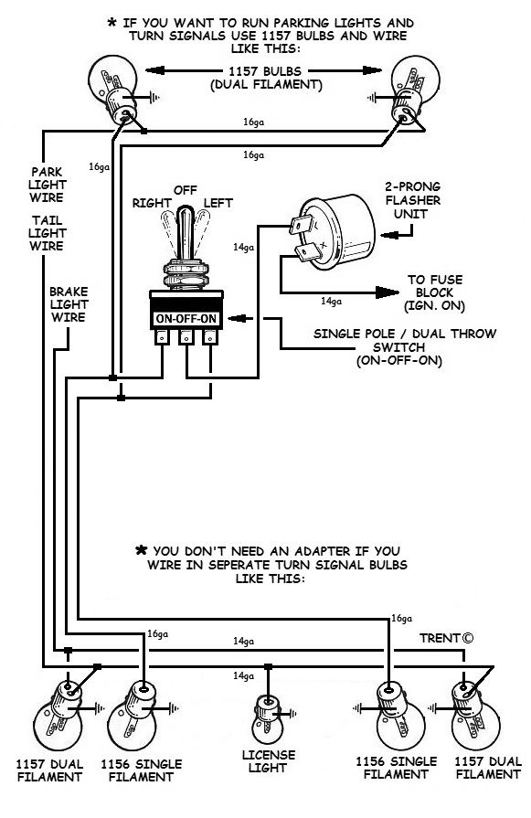 I think this goes along with it;
__________________
What's right about America is that although we have a mess of problems, we have great capacity - intellect and resources - to do some thing about them. - Henry Ford II |
|
|
|
| Sponsored Links (Register now to hide all advertisements) |
|
|
|
06-04-2015, 11:04 PM
|
#3 |
|
Senior Member

Join Date: May 2010
Location: Mpls, MN
Posts: 27,582
|
Here's the basic schematic for the 3 prong flasher.
|
|
|
|
|
06-05-2015, 04:30 AM
|
#4 |
|
Senior Member
Join Date: Jul 2013
Location: Johnstown, PA.
Posts: 137
|
Thanks
|
|
|
|
|
06-05-2015, 05:59 AM
|
#5 |
|
Senior Member

Join Date: Aug 2012
Location: Adrian , Mich.
Posts: 386
|
Divco one , I used the diagram Mike V. Florida shows last year , using the same style switch , and worked great . Good Luck
|
|
|
|
|
06-05-2015, 07:58 AM
|
#6 |
|
Member
Join Date: Oct 2010
Location: Stillwater, MN
Posts: 64
|
Sponsored Links (Register now to hide all advertisements)
|
|
|
|
|
06-05-2015, 09:08 AM
|
#7 |
|
Senior Member

Join Date: May 2010
Location: Windy City
Posts: 2,919
|
There are two problems with this type of signal setup:
1) There is no interruption or flashing of the brake filament if you are 'on the brake'. What is seen and perceived visually from the rear, at a distance, is a 75% weaker signal. It may look OK in the garage, but what is seen outside in daylight traffic is altogether different. That is why 7 (or 8) wire switches that incorporate the brake signal separately to LR and RR are used. DOT recognizes this and new vehicles must have interruption of the brake light with a signal. 2) The three-circuit tail lamp bucket conversion you need to do to use both an 1157 and 1156 bulb (or their 6V equiv.) will leave you with some challenges, including which section of the lens (upper/lower) will do what? I'll stick with my Signal Stat 900. I don't want to get rear-ended 'cause somebody didn't clearly recognize my turn signal while I was on the brake. Their tiny, smart-phone distracted brains have been trained to respond only to DOT compliant signal formats! |
|
|
|
|
06-05-2015, 10:02 AM
|
#8 |
|
Senior Member

Join Date: Nov 2010
Location: Sebastian, FL
Posts: 479
|
Does the Signal Stat 900 work with 6 volt??
|
|
|
|
|
06-05-2015, 12:37 PM
|
#9 |
|
Senior Member

Join Date: Jan 2012
Location: Phoenix, Oregon
Posts: 661
|
I would add 4 way to it. The way most people do it is to go to the three way switch and go to one outside pole (on) thru' a simple on/off switch to the other outside pole.
It works but you have to have a blinker on, then throw the on/off switch. Personally I'd use a DPST and wire the input together; the input being from the flasher.
__________________
Mike Stitt "A business that make nothing but money is a poor business." -Henry Ford |
|
|
|
|
06-05-2015, 01:44 PM
|
#10 | ||
|
Senior Member

Join Date: Nov 2010
Location: Anchorage, Alaska
Posts: 9,115
|
Quote:
Quote:
Jim -- Yes, the only difference is the flasher and the pilot bulb need to be whatever voltage you want. Easy swap if you happen to have the wrong voltage.
__________________
Alaskan A's Antique Auto Mushers of Alaska Model A Ford Club of America Model A Restorers Club Antique Automobile Club of America Mullins Owner's Club |
||
|
|
|

|
06-05-2015, 01:57 PM
|
#11 |
|
Senior Member

Join Date: Jul 2010
Location: west coast Fla..
Posts: 311
|
I have the LED lights for the tail lights and would like to add turn signal, I was told by Mikes than a resistor will have to be used. Where can I get them and how is it wired? Can it be used with cowl lights original bulbs?...thanks
|
|
|
|
|
06-05-2015, 02:09 PM
|
#12 | |
|
Senior Member
Join Date: Nov 2010
Location: Anchorage, Alaska
Posts: 9,115
|
Quote:
I actually bought an electronic flasher when I got the LED tail lights, and it worked fine until I started the engine. Then it quit. Turn the engine off and worked just fine. Solution was to put the original flasher back in and everything was back to normal. Again, no resistor.
__________________
Alaskan A's Antique Auto Mushers of Alaska Model A Ford Club of America Model A Restorers Club Antique Automobile Club of America Mullins Owner's Club |
|
|
|
|
|
06-05-2015, 07:15 PM
|
#13 |
|
Senior Member
Join Date: May 2010
Location: Mpls, MN
Posts: 27,582
|
My electronic flasher will work with LED bulbs and no reisistor.
|
|
|
|
|
06-06-2015, 05:54 AM
|
#14 |
|
Senior Member
Join Date: Nov 2010
Location: Sebastian, FL
Posts: 479
|
Tom, What flasher are you using?
|
|
|
|
|
06-06-2015, 02:32 PM
|
#15 |
|
Senior Member
Join Date: Nov 2010
Location: Anchorage, Alaska
Posts: 9,115
|
I actually think I had something amiss when my electronic flasher wouldn't work. I intend on chasing that down one of these days. It makes a loud enough "click" that I can hear it whereas the analog one does not.
Here is the spec sheet on the one I have:
__________________
Alaskan A's Antique Auto Mushers of Alaska Model A Ford Club of America Model A Restorers Club Antique Automobile Club of America Mullins Owner's Club |
|
|
|
|
06-06-2015, 02:44 PM
|
#16 |
|
Senior Member
Join Date: Jul 2013
Location: Johnstown, PA.
Posts: 137
|
With 6 volt cowl bulbs and 6 volt LEDs mounted on the rear bumper, a regular 6 volt flasher volt works perfectly. I'm going to add a buzzer so I know when they are on.
|
|
|
|
|
06-07-2015, 08:15 AM
|
#17 | |
|
Senior Member
Join Date: May 2010
Location: Mpls, MN
Posts: 27,582
|
Quote:
|
|
|
|
|
|
«
Previous Thread
|
Next Thread
»
 Linear Mode

|
|

| Sponsored Links (Register now to hide all advertisements) |
|
|
All times are GMT -5. The time now is 09:17 AM.