|
|||||||


| Sponsored Links (Register now to hide all advertisements) |
|
|
 |

|
Thread Tools | Display Modes |
 02-18-2024, 11:00 AM
|
#1 |
|
Member
Join Date: Apr 2019
Location: Orange County, CA
Posts: 73
|
I've been searching through past posts on handbrakes and have not seen too much in the way of schematics of the insides of a handbrake. I'm getting ready to take the innards out of my old handbrake and installing in a new one. If anyone has any diagrams it would be most appreciated.
|

|

|
|
02-18-2024, 01:01 PM
|
#2 |
|
Senior Member

Join Date: Jul 2010
Location: Cow Hampshire
Posts: 4,188
|
Define "handbrake."
Are you referring to the left handed frame mounted early "AR" pistol grip type handle. Or the transmission front "pistol grip" handle? Or the transmission front "pushbutton" handle? Or the transmission side "pushbutton" handle? None of these are exactly the same - in fact a major point of confusion in the sales of these items concerns the "pawl" used to engage the ratchet. The common complaint being "my vendor didn't send the right pawl." The pushbutton "front" and pushbutton "side" are different in the construction of the "handle top" with the front version cast in one piece and containing the spring and the side version made up of sheet steel and bent to shape and attachment, spring applied nearer the ratchet. Or - perhaps you're referring to the actual "emergency brake" shoes/carrier which of course is applied only to the rear wheels - and are pretty much the same differing only in placement of springs and seals. Or perhaps you're referring to the "AR" emergency brake (Left Hand Frame attached handle) which is actually made to activate ALL FOUR WHEEL service brakes. Not too many of these survived modification to the later pattern. Re-read: It sounds like you need instruction on the handle(s)? Joe K
__________________
Shudda kept the horse. |
|
|
|
| Sponsored Links (Register now to hide all advertisements) |
|
|
|
02-18-2024, 01:46 PM
|
#3 |
|
Member
Join Date: Apr 2019
Location: Orange County, CA
Posts: 73
|
Sorry, I should have stated such. I'm looking for the transmission side pushbutton.
|
|
|
|
|
02-18-2024, 01:48 PM
|
#4 |
|
Member
Join Date: Apr 2019
Location: Orange County, CA
Posts: 73
|
And yes, just the handle. I purchased a nicely done butler finish handbrake, so I'm transferring/inspecting the guts of my old handbrake into the new.
|
|
|
|
|
02-18-2024, 02:21 PM
|
#5 |
|
Senior Member

Join Date: May 2010
Location: Clinton,WA/Whidbey Island
Posts: 4,105
|
This help?
__________________
www.whidbeymodelaclub.com |
|
|
|
|
02-18-2024, 04:40 PM
|
#6 | |
|
Senior Member
Join Date: Jul 2010
Location: Cow Hampshire
Posts: 4,188
|
Sponsored Links (Register now to hide all advertisements)
Quote:
The parts for these are available reproduced. Originals have a tendency to "embrittle" between the top and the part pressed into the vertical shaft. Pot metal. For the handle to right side version, one can see the assembly of these looking at the usual vendor pix. Below see the lever complete. Important things for re-assembly would be the top button and rod (small pin holds these together), the spring below the button, the orientation of the ratchet part compared to the handle "top" below the button, and the orientation of the bolt holding it together. Note the top of the handle (where the button is pushed into) is made from a single piece of metal "crimped" over a matching tang on the vertical. Very obviously Ford's constant quest for economy in construction. He probably made the top piece out of a trimmed piece removed from the bottom cut-out of the handle. Most all these parts are reproduced - or you can buy a nearly as original repop of the entire handle - the quality is pretty good actually. 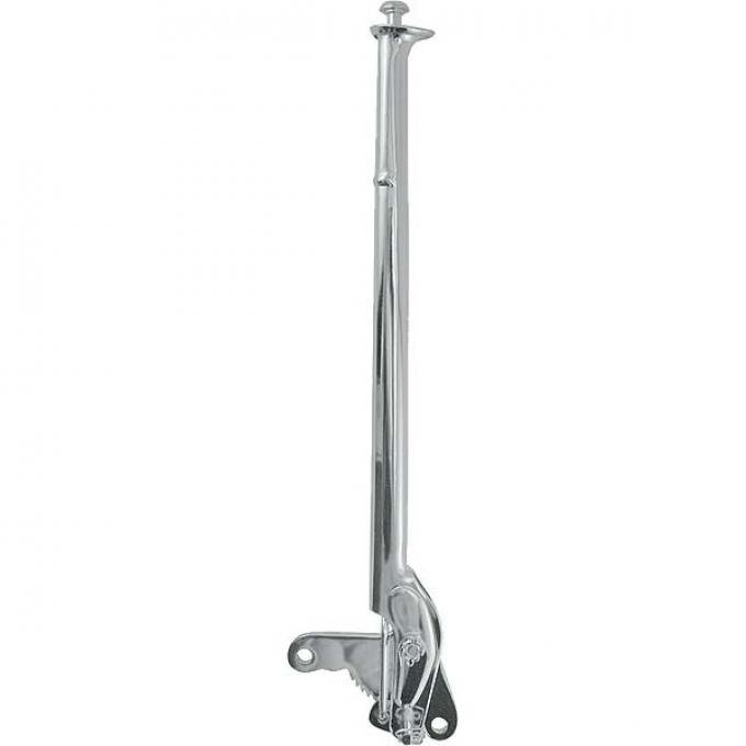 Joe K
__________________
Shudda kept the horse. Last edited by Joe K; 02-18-2024 at 05:05 PM. |
|
|
|
|

|
02-18-2024, 07:52 PM
|
#7 |
|
Member
Join Date: Apr 2019
Location: Orange County, CA
Posts: 73
|
Thanks much to both Joe K and Gary WA -- both help in giving me guidance.
Gary, how is the weather up your way. My parents live in Silverdale and my sister in Suquamish. Used to have friends that lived in both Mukilteo and Clinton. |
|
|
|
|
02-19-2024, 10:59 AM
|
#8 | |
|
Senior Member
Join Date: May 2010
Location: Clinton,WA/Whidbey Island
Posts: 4,105
|
Quote:
__________________
www.whidbeymodelaclub.com |
|
|
|
|
|
02-19-2024, 11:58 AM
|
#9 |
|
Member
Join Date: Apr 2019
Location: Orange County, CA
Posts: 73
|
Good to hear. I was born and raised in North Seattle area so I know the terrain. Relatives lived in Port Gamble so we frequented the Edmonds-Kingston Ferry many a time. I'm hoping to drive my Model A up the 101 in early June from Orange County, CA to Silverdale, WA. It will be one of my more memorable drives if it all comes together.
|
|
|
|
|
02-19-2024, 04:15 PM
|
#10 |
|
Senior Member

Join Date: Jun 2010
Location: San Antonio, Texas
Posts: 16,436
|
There are actually two different types of side E-brake lever assembly. The difference is how the locking rachet is mounted. The width of the rachet and their teeth are different as well as the way the two rachets are mounted. One is pointed side up and the other is pointed side down.
Last edited by rotorwrench; 02-19-2024 at 04:21 PM. |
|
|
|
|
02-20-2024, 09:56 AM
|
#11 | |
|
Senior Member
Join Date: Jul 2010
Location: Cow Hampshire
Posts: 4,188
|
Quote:
The later handles (B and beyond) are notable in having a "bend" in the handgrip portion of the handle. Not to say that there wasn't points up version. Sometimes Ford is a little hard to pin down to "a design." Information is a good thing - if you can provide more - even a pix of an extant. Joe K
__________________
Shudda kept the horse. |
|
|
|
|
|
02-20-2024, 06:01 PM
|
#12 |
|
Member
Join Date: Apr 2019
Location: Orange County, CA
Posts: 73
|
Another question for you all. Im told that the felt anti-rattle piece is a good thing to include when rebuilding. Brattons and Macs carries it, but no one else seems to. Pictured is the one from Brattons/Macs. Anyone think the anti rattle felts used for the idle/advance rods might work? CW Moss carries these and they are only a 20 min drive and no shipping costs! Of course felt from Hobby Lobby might be just as good.
|
|
|
|
|
02-20-2024, 07:26 PM
|
#13 |
|
Senior Member
Join Date: Jun 2010
Location: San Antonio, Texas
Posts: 16,436
|
The rachet is triangle shaped with bolts front and rear to mount it to the side of the transmission. The apex of the triangle is what I was referring to, not the ratchet teeth even though both are on the bottom. My mid 1929 car has the earlier type with the apex pointing down. This type lowers the lever an inch or so. The pawl is still mounted on the bottom of the lever but not exactly like the later version.
The one in the photo on post #6 is the late type that was used till end of model A production and beyond into the model B era. The green book doesn't always cover earlier versions of parts. If your early side lever breaks then they offered the late type lever as a complete replacement. Even reproduction parts don't always offer parts for all types of assemblies and separate parts. This link is an example of the early type. It's not a real good photo but that's it. https://www.ebay.com/itm/13479456620...hoCyNIQAvD_BwE Last edited by rotorwrench; 02-20-2024 at 07:36 PM. |
|
|
|
|
02-20-2024, 08:53 PM
|
#14 | |
|
Senior Member
Join Date: Jul 2010
Location: Cow Hampshire
Posts: 4,188
|
Nice. Well described. Thanks for the pix. I have three of the later version (one of these a repop) and had no idea that something else existed.
I can see how shaping the ratchet differently could "lower" the pivot point and handle. Quote:
As I said, Ford didn't exactly "pin down" design. A lot of variants may come from changing subcontractors. Back-fit was (mostly) another matter. Somebody will search and see these posts and have an AhHa! moment. I do this a lot myself in research here. Joe K
__________________
Shudda kept the horse. Last edited by Joe K; 02-20-2024 at 09:20 PM. |
|
|
|
|
|
«
Previous Thread
|
Next Thread
»
 Linear Mode

|
|

| Sponsored Links (Register now to hide all advertisements) |
|
|
All times are GMT -5. The time now is 06:32 AM.