|
|||||||


| Sponsored Links (Register now to hide all advertisements) |
|
|
 |

|
Thread Tools | Display Modes |
 07-17-2012, 05:39 AM
|
#21 |
|
Member

Join Date: Jul 2010
Location: NETHERLANDS
Posts: 67
|
Mart, love your work methods. Did i miss something or is OldRusty now without an engine ? BTW, those '32 grille shells on the wall, are they the same ones ..........? ?
|

|

|
|
07-17-2012, 06:00 AM
|
#22 |
|
Senior Member

Join Date: May 2010
Location: Solihull, England.
Posts: 8,756
|
Hi Henry. I fitted a French motor to Old Rusty last year, so this one was sitting idle. Ideal for this job as it's a known running engine.
One of those grille shells is from the original haul. It is being saved for Old Rusty. The other one is the one from/for my 32 sedan. Thanks for all the other comments fellas. Mart. |
|
|
|
| Sponsored Links (Register now to hide all advertisements) |
|
|
|
07-17-2012, 07:22 AM
|
#23 |
|
Senior Member

Join Date: Dec 2011
Location: Houston Texas
Posts: 170
|
Thanks for sharing keep sending progress pics
|
|
|
|
|
07-17-2012, 07:55 AM
|
#24 |
|
Senior Member

Join Date: May 2010
Location: ManchVegas, New Hampshah
Posts: 1,589
|
Nice save. I like your engineering on the chassis fixes. The condition of the original engine looks like it was in a few floods. Again, great work.
|
|
|
|
|
07-17-2012, 08:00 AM
|
#25 |
|
Senior Member

Join Date: May 2010
Location: Kokomo, Indiana
Posts: 1,731
|
Very impressive!! I like your approach. Good luck and continued success.
|
|
|
|
|
07-17-2012, 09:04 AM
|
#26 |
|
Senior Member

Join Date: Feb 2011
Location: Candiac, Qc.
Posts: 483
|
Sponsored Links (Register now to hide all advertisements)
Robert |
|
|
|
|
07-17-2012, 09:52 AM
|
#27 |
|
Senior Member

Join Date: May 2010
Location: new britain,ct 06052
Posts: 9,390
|
This is an amazing thread. And it shows a lot of how thing s were done back before the i/net and 1-800 order partd.
Thanks for posting! ! Paul in CT |
|
|
|
|
07-17-2012, 11:31 AM
|
#28 |
|
Senior Member

Join Date: Jun 2010
Location: St Croix Falls WI
Posts: 2,080
|
Congrats on the nice 33 , IF you have the patience you can take the primer off by color sanding . This 33 5w sat for a loooong time in that little metal roofed garage . The pic of it coming out is from DEC 2010 . The spare grille in the first pic was just put on for a photo op . I got it painted red . As you can see it is really quite nice after a couple hours with paint stripper . May wanna try this on yours . If pitted bad or whatever you can just paint it again . Bumpers also . On the body as you can see mine had the primer thing done to it also . Quite a few hours CAREFULLY color sanding [ used steel wool , 1000 , 600 & 1200 to remove the primer . No idea whats under yours but I found most of the gennie paint - some striping & NO OLD BODYWORK . Car isn't real pretty but it goes down the road fine & gets a lot of phones pointed at it . The last pic is how it looked about halfway done . The steel wool worked best in the thinner primer areas with the sandpaper working the best on thicker areas . I only used the sandpaper until the gennie paint started peeking through & finished with the steel wool . Easier to control the removal with it as it is not as agressive . If you want to buff it leave just a trace of primer & buff it off . I just left mine dull as the paint is missing in some areas etc . You may or may not be interested but it does work with patience . GOOD LUCK
Last edited by David J; 07-18-2012 at 03:03 AM. Reason: ADD PIC |
|
|
|
|
07-17-2012, 11:59 AM
|
#29 |
|
Senior Member

Join Date: May 2010
Location: Kansas
Posts: 334
|
Love your car, Get that baby running and drive the thunder out of it...
__________________
[QUO[/QUOTE]no matter where you are,or where you're at, there you are... 
|
|
|
|
|
07-17-2012, 12:18 PM
|
#30 |
|
Senior Member

Join Date: May 2010
Location: Coral Springs FL
Posts: 10,951
|
Great work. Please don't use 3 legged jack stands. They just don't have the stability of 4 legged stands. Google '3 legged jack stand safety" and info. like this appears. http://www.aa1car.com/library/floor_jacks.htm
Last edited by 19Fordy; 07-17-2012 at 12:36 PM. |
|
|
|
|
07-17-2012, 01:54 PM
|
#31 |
|
Senior Member

Join Date: May 2010
Location: Sf bay area
Posts: 1,464
|
Mart--thankyou for sharing enjoyed your post and learned some front end stuff....gump
|
|
|
|
|
07-17-2012, 02:04 PM
|
#32 |
|
Senior Member
Join Date: May 2010
Location: Alameda, California
Posts: 335
|
Well, I'm blown away......If you had been on the Titanic it would have made it to New York!...Verrrry impressive.... I don't think I would have recovered from looking in the oil pan.........Matt in Alameda
|
|
|
|
|
07-17-2012, 02:28 PM
|
#33 |
|
Senior Member

Join Date: Jul 2010
Location: Quebec, Canada
Posts: 415
|
VERY impressive Mart. Thanks for sharing.
|
|
|
|
|
07-17-2012, 02:35 PM
|
#34 |
|
Senior Member
Join Date: May 2010
Location: Solihull, England.
Posts: 8,756
|
Ok, Boys. lets have a look at what happened next.
The next few posts will cover mid May to Mid June. ========================================= 5/15/12 Have done a little more, namely the front shocks. I find that deciding how to do it takes longer than the actual doing. And once the first side is done, copying it for the other side is quicker still. I decided on a similar method to the rear. Started by drilling a hole straight through the radius arm. 1/2" first, then opened the outer to 5/8". 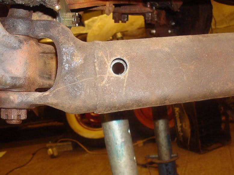 I then turned one of the 5/8" shafts down to 1/2" to suit the bushes in the shocks I had decided to use, and knocked it through the arm as a test. 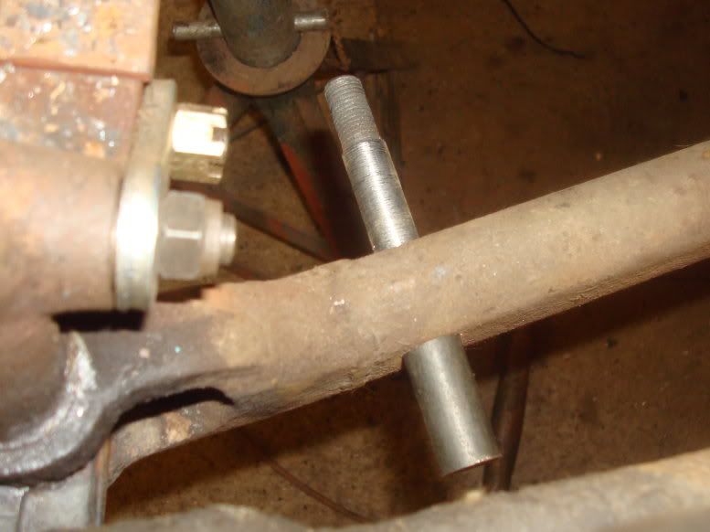 Once happy that this was to be a going concern, I cut down the pin, tidied the end and knocked it in again. It's a good tight fit. 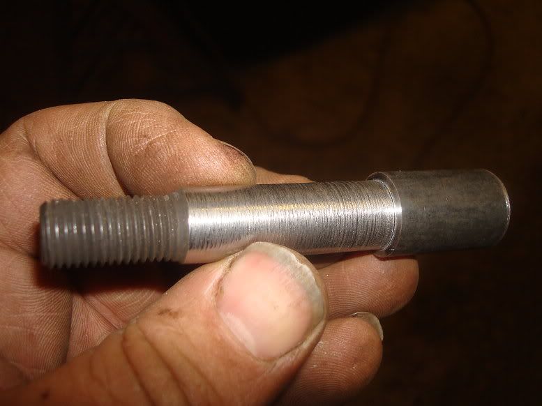 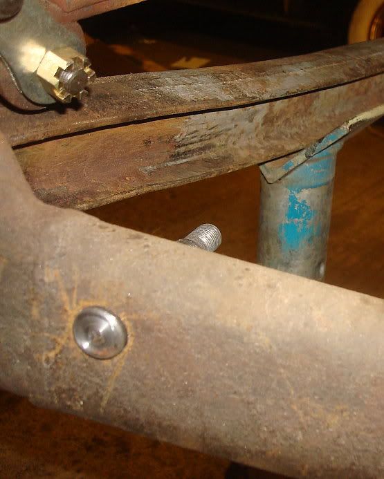 I thought about welding it in, but with the stepped diameters, it will be held solid by the nut so I will leave it just as it is. It did occur to me after doing the job that this location for the shox would not suit a setup where the track rod is above the radius rods. No problem for me, as mine runs below, but could be a problem if not taken into account. The location I chose for the lower mount puts the shock in alignment with the rear edge of the fender brace. On the 33/34 the brace is a substantial affair, and has an extra brace running through the inner fender panel to the front crossmember. I decided to simply mount the upper part of the shock to the brace using a bolt on mount similar to that used at the rear. Here's the brace: 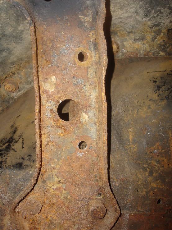 The top and large holes are stock, I drilled a new hole lower down. Here's the raw materials for the upper mount: 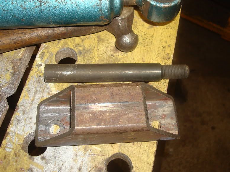 And welded up into a mount: 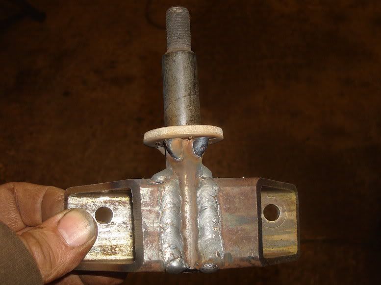 And a couple of shots with the shock bolted up: 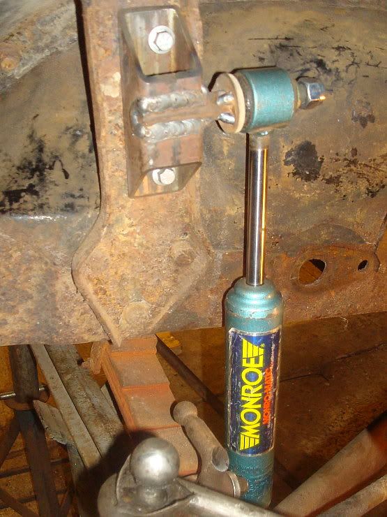 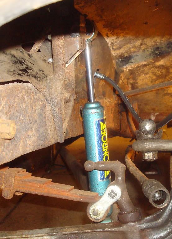 Not the prettiest of installations, but it will do the job and it's just another job that needed to be sorted, because without it, the car cannot go for test. As I have said before, it's only metal, anything you do can be undone. Looking at that last pic, I'm thinking the drag link ought to be the next thing to get some attention! Personally, I'm pleased with it, particularly the aspect that it has all been done with stuff I had around me. Just found an extra pic showing both ends at once: 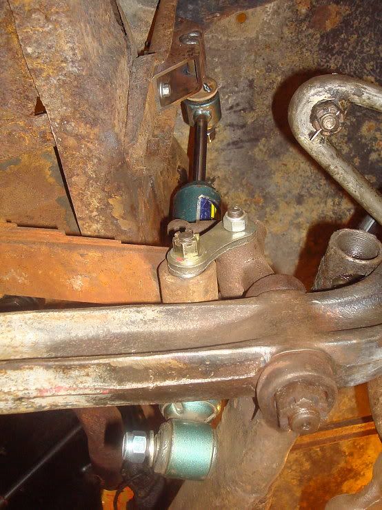 Mart. ============================================ 5/19/12 Here's a mini-update to log the work done over the last few days. Just little stuff. I made up the parts for the right hand front shock absorber, and it came out ok, except that when I welded the parts up I managed to weld them up the wrong way around so I had one that was more like a left hand one than a right hand one. Whoops. I welded up the bolt holes and redrilled them the other way round. So with the shocks sorted, I turned my attention to the drag link. This was a mess, it had been cut and welded to shorten it, (right in the middle which is the worst place to do it,) and bent and had something welded to it. Before I got the car, I saw an A drag link for sale (one out of Tony Cardy's stash), and having saw a pic of the 33 drag link and seeing it was messed up, I bought it just in case it may be useful. Here's the pic I saw: 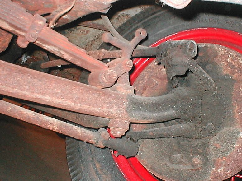 And a close up of the dodgy bit: 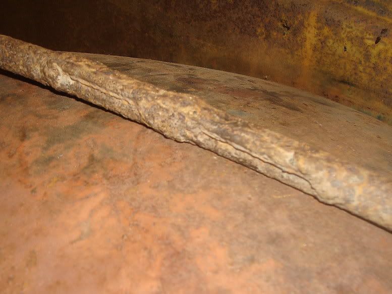 I got the 33 one off, and put it next to the A. 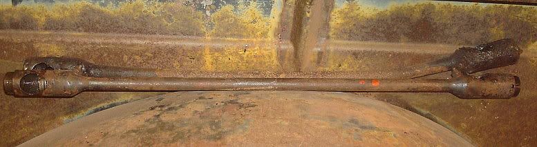 The length was very similar, the A one less than 1/8" shorter than nthe cobbled up 33. So I had something I could use - that's good, I don't like messing with the drag link. The other thing that wasn't right was the pitman arm. It had been bent. God knows why, but it had. I heated it and bent it straight again. 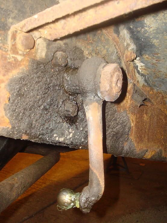 I said earlier the guy that had this back in the day was not afraid to grease stuff, so to my relief, I could see the ball on the pitman arm was in good condition. I could feel some play in the steering box, so without too much drama, adjusted it until it felt ok in the mid point. 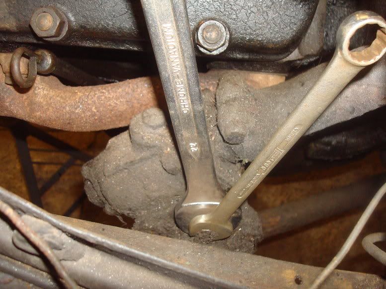 The big spanner is on an eccentric that you turn to alter the relationship between the worm and sector. I just slackened the four nuts, turned the eccentric while feeling if the play was increasing or decreasing, and set it at the minimum, but not binding. Do the 4 nuts up and job done. I dismantled the A and 33 drag links, and a 32 track rod and salvaged the best parts from the 3. I had a set of repro parts to rebuild, but they were not good. It was as if they had been copied off worn parts, not NOS stuff. The radii of the cups did not match the balls, so what's that all about? I assembled it up with good original parts, fitted new rubber seals at each end and assembled the A drag link onto the car. 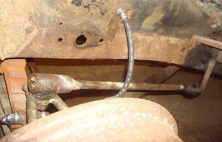 And while I was in the area I put new rubber boots on the track rod ends. 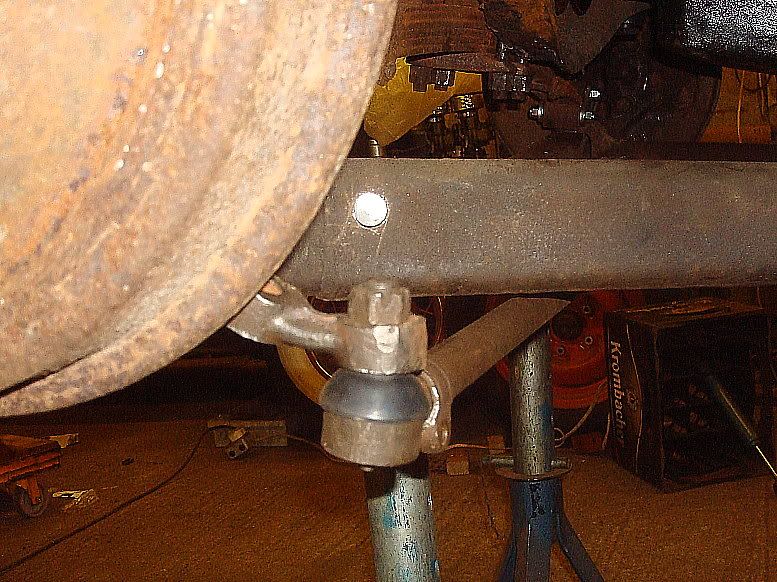 I tested the steering through full lock to lock operation, and it now turns smoothly through the whole range. When I got it, it bound up terribly towards the ends of each lock. Track rod rubbing the radius arms, conflicting arcs on the drag link and bent pitman arm all made for a very badly engineered setup. I have a theory why the drag link was shortened. The spindles were swapped out for 37-41 roundbacks when the brakes were switched to hydraulic. The 32-34 spindles have an integral steering arm which is correctly aligned to be at 90 deg to the drag link, which means the end is forward of the axle centre line. when switching to a bolt on aftermarket slingshot arm, the arm is at 90 deg to the spindle, and the end is on the axle centre line, not forward of it. Hence the need for a shorter drag link. I reckon the A link is slightly short, but closer to the ideal length than a stock 33. An adjustable one is do-able, but if trying to retain the simplistic beauty of Henry's original design, I prefer the one piece original style unit. I still need to go around and fit lots of split pins, which would make sense to do while the car is up in the air, but that's the finishing touches, I'm still tackling big job-stoppers, stuff that is preventing it being driven. Still lots to do, but good solid progress made. Mart. |
|
|
|
|
07-17-2012, 02:37 PM
|
#35 |
|
Senior Member
Join Date: May 2010
Location: Solihull, England.
Posts: 8,756
|
Next I looked at the fuel tank.
======================================== 5/22/12 447 I just came in from a good sesh so I'll bring things up to date. I finished messing with the shocks, fitting the painted front shox and brackets, and putting washers and nylock nuts on. I started thinking about what is the next job stopper. The fuel tank. When I was under the back end I noticed the underseal was shiny and gooey on the one corner of the tank. I looked up with a torch and had a poke around with a chisel. Sure enough I found a couple of pinholes. 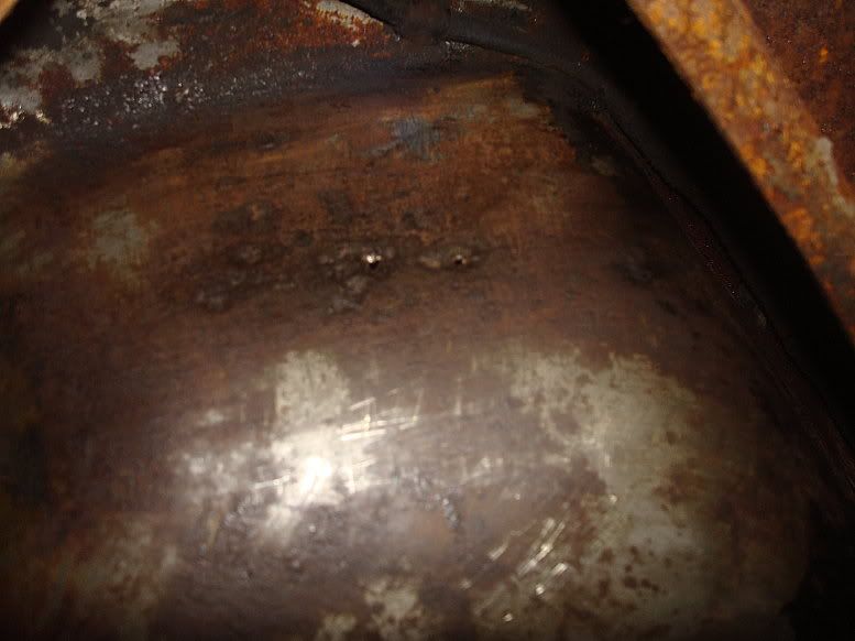 This is after cleaning some of the underseal off. I looked and realised getting the tank out is quite a job. But out it had to come. Quick check on the internet: "take the bumper off. remove the rear panel. Remove the spreader bar, undo the tank, slide it out." Piece of piss. Had to get the big breaker bar out on the bumper bolts, but got the bumper off. I drilled the 4 screws out that held the rear panel on and removed the fender to rear panel bolts. Some of these are into cage nuts so I was pleased when they came out ok. Here's the rear end with the bumper and rear panel removed: 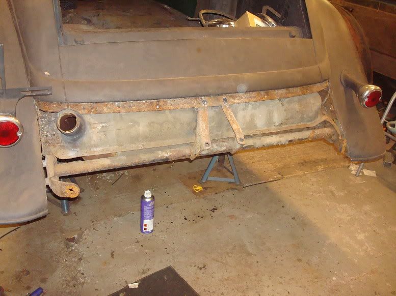 Spreader bar came off ok, and revealed the bolts holding the tank in: Right hand: 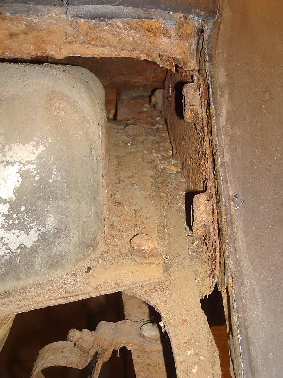 And left: 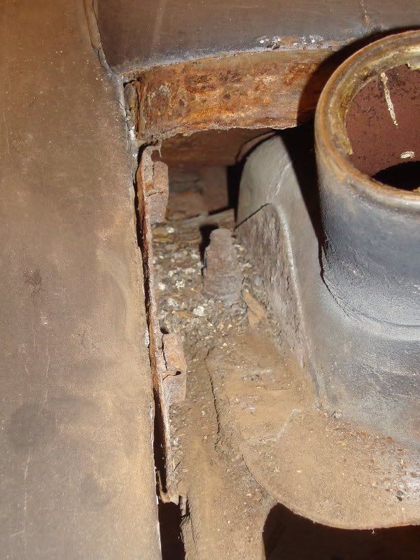 I could see the left mount was wound down tighter than it should be, so I knew the tank must have been removed at some time in the past. I couldn't undo the nuts so I removed the filler panels on each side to get better access. Once I did that I could undo the nuts and bolts. 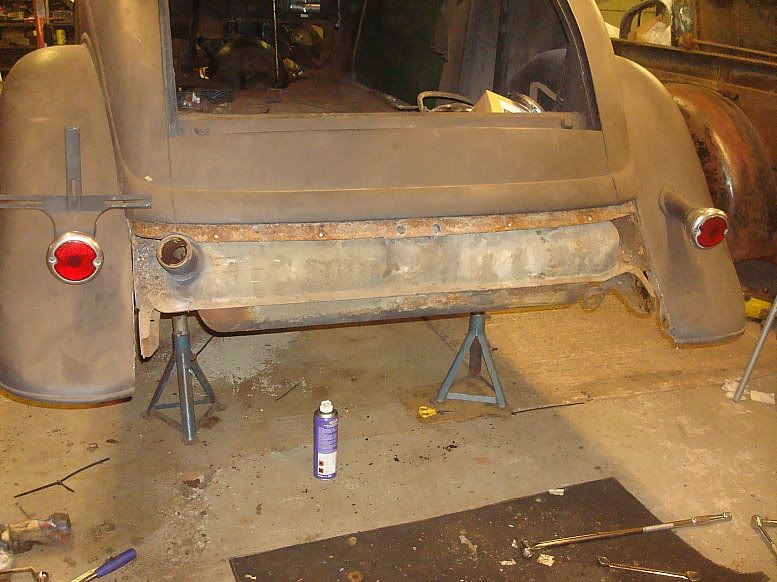 When it was half way out I could see then that a second sender unit had been added. 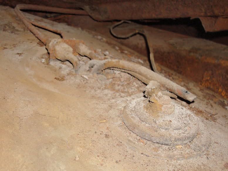 So that is why the tank had been disturbed previously. I removed the fuel pipe and capillary (still the originals). And out it came: 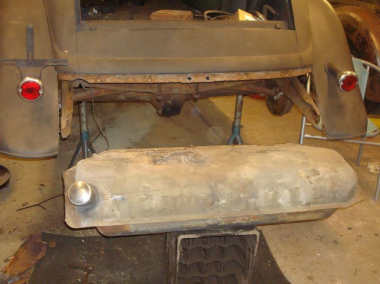 I could then see the holes that needed repairing: 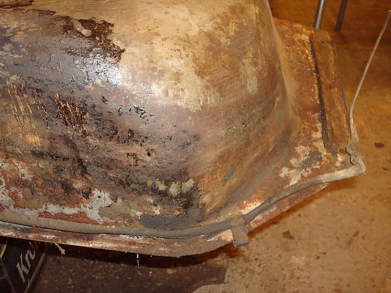 Not too bad really, I thought. I cleaned it all up with a wire brush (on the angle grinder) 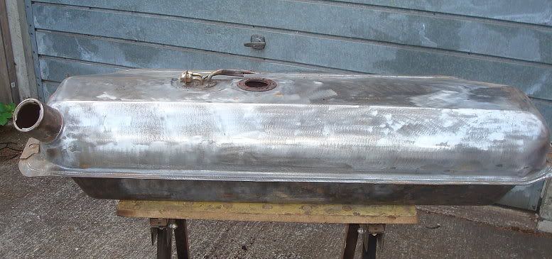 And tipped it on end and all this crap came out of it: 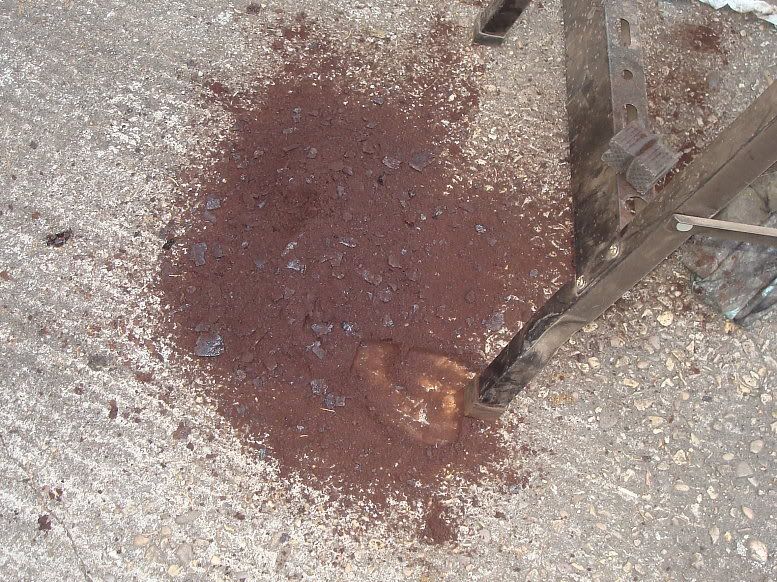 I was torn between repair techniques. Glassfibre? Solder? Self tappers and solder? I dragged it back in the garage and said Fuck it. I'll gas it. 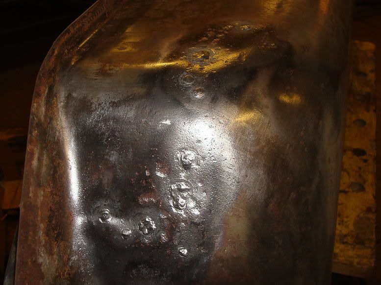 Didn't kill myself, so it was a good choice. I gave it a coat of red oxide with the roller and left it in the sun to dry out (I had flushed it through with water). 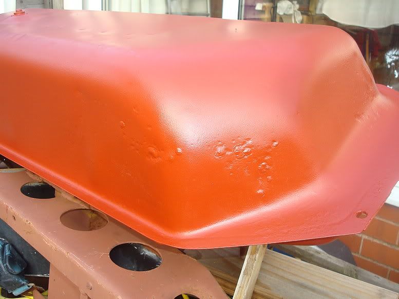 I just happened to take a shot of the back of the car with the arse end hanging out: 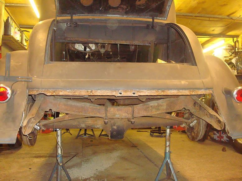 I looked at the sender units I had and decided to use a Pilot unit I had around. This neat unit fits the 33 6 bolt pattern. 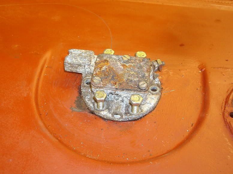 That was last night. I couldn't go any further because I hadn't got any new screws to fit the sender. The old ones were a bit knackered after being removed. |
|
|
|
|
07-17-2012, 02:37 PM
|
#36 |
|
Senior Member
Join Date: May 2010
Location: Solihull, England.
Posts: 8,756
|
Fuel tank continued
Mart. =========================================== I got up this morning and there was a thought nagging at me. When fitting the sender I could see there was some clag in the bottom of the tank. I remembered Lars Brandow's 33 build and he got drastic with his tank, and that is what I decided to do too. Marked the top of the tank: 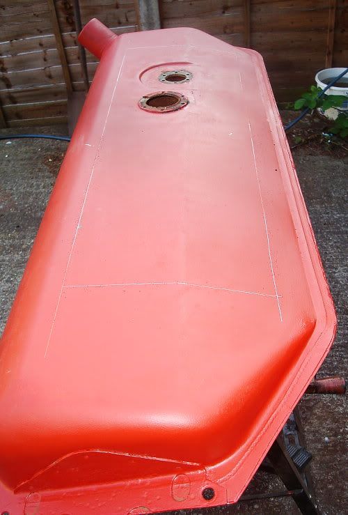 And cut it out with a thin disc. 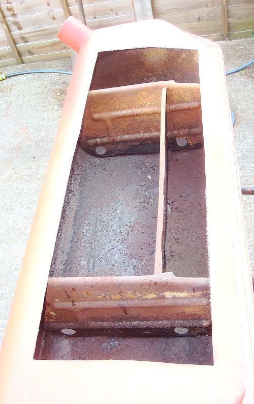 You can see the yucky mess. Yuck- 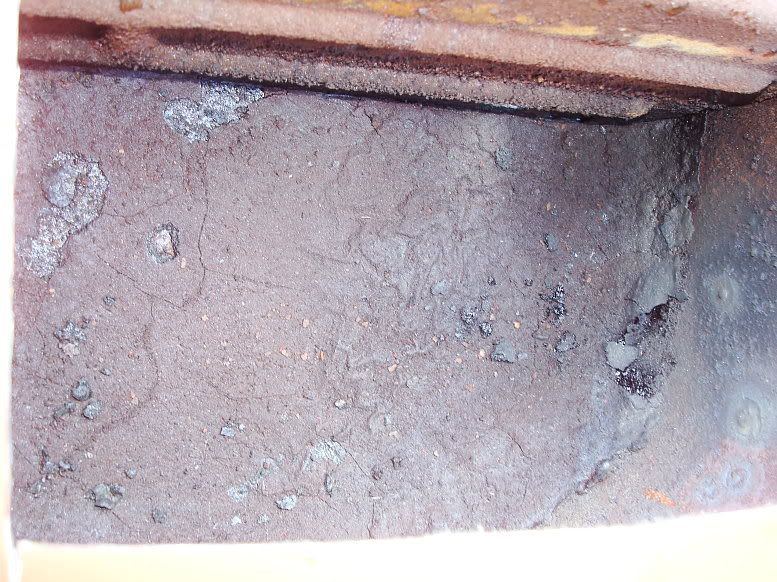 ee- 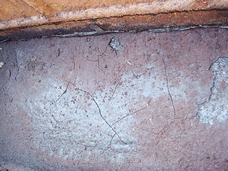 Mess: 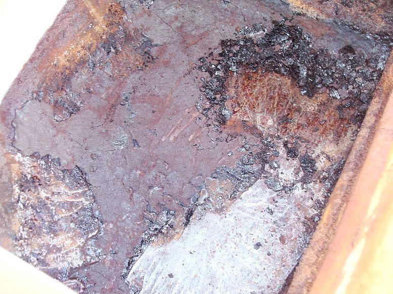 This is half way through scraping it out. I didn't want to use any solvents because I wanted to be able to weld it back up. I got it all out: 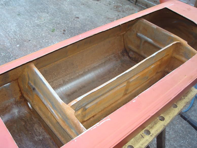 And after welding up the extra sender hole, I put the top back on: 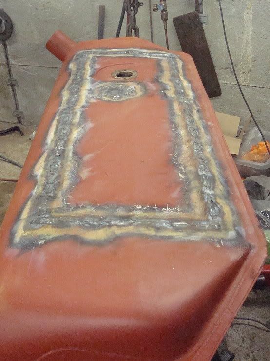 And after a quick run round with a wire brush: 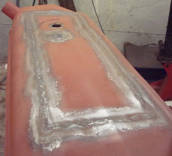 Slapped another coat of paint on with the trusty roller. (Wrapped in cling film and ready to go at a moments notice) 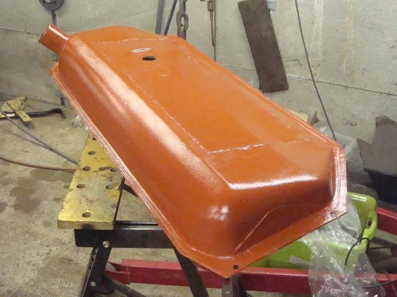 I migged it at intervals (down to 20mm) and gas welded it. I got a little distortion, but not too bad. As it is a closed section, I couldn't hammer and dolly it, so it was just a case of skipping around and keeping the heat to a minimum. I would have liked it better, but it won't be on show, and functionally should be fine. It'll certainly be better than if I'd left it with all that shite in there. So that's how it stands as I left the garage this evening. Feeling pretty pleased I went the extra mile on the tank. Mart. |
|
|
|
|
07-17-2012, 02:41 PM
|
#37 |
|
Senior Member
Join Date: May 2010
Location: Solihull, England.
Posts: 8,756
|
5/29/12
Been plugging away at it and have another little bit of progress to report. I ran a new fuel pipe. The one in the car was the original, and had then capillary tube brazed to it as orig. But it was badly pitted, unfortunately, and I don't need the capillary as I'm going electric, so out it came. I fitted the sender with a new gasket and hooked up the pipe and got the tank in place. 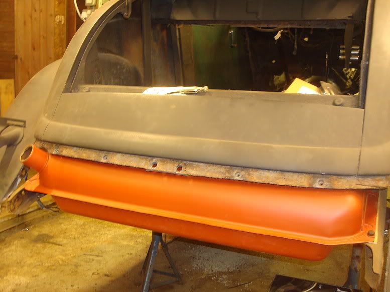 I then refitted all the rear end sheet metal and spent ages trying to find some suitable bolts for the rear panel. Refitted the spreader bar and the rear bumper. Used new bolts as I sheared one getting it off. Why I didn't free it with Oxy I don't know. Had a day out last Friday and went to Enfield with some mates. Trawled the swap meet and picked up a few nik-naks. One of the things I got was this Pilot oil filler/fuel pump stand for a tenner. It looks like new, but is lightly used. Best thing is, it is long, and the base is nice and flat (almost). 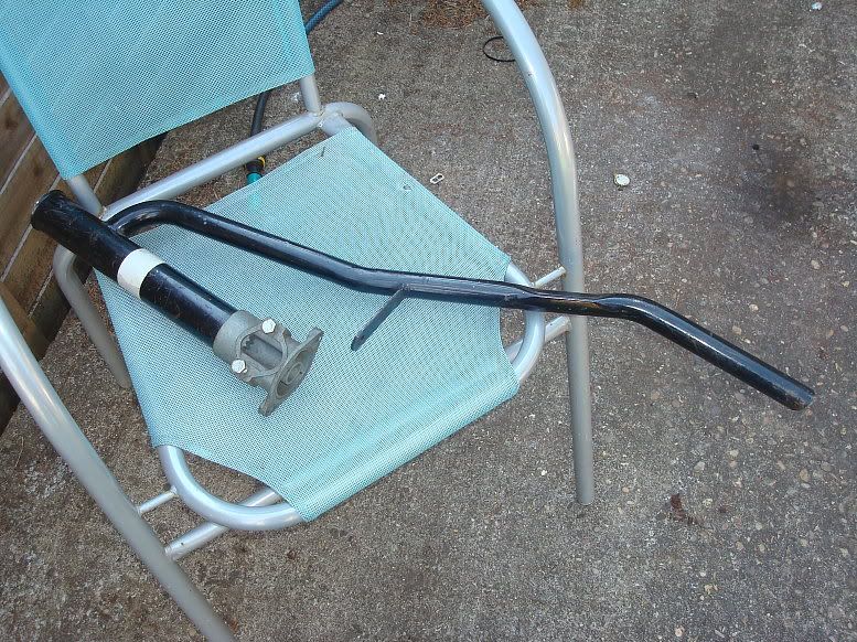 I cut it down to a suitable height and set it in place. I don't know quite what the crack is, but the filler tube is just fouling the firewall: 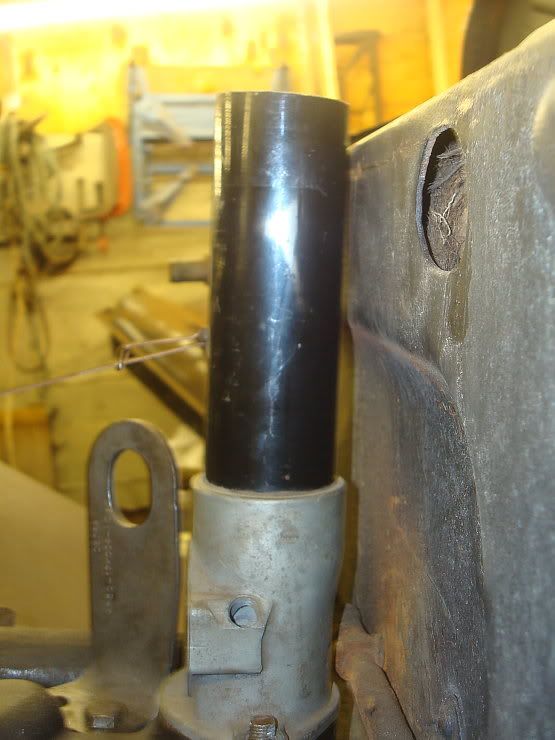 I didn't want to pie cut it, so tried to bend it a bit by heating and quenching on the front side. 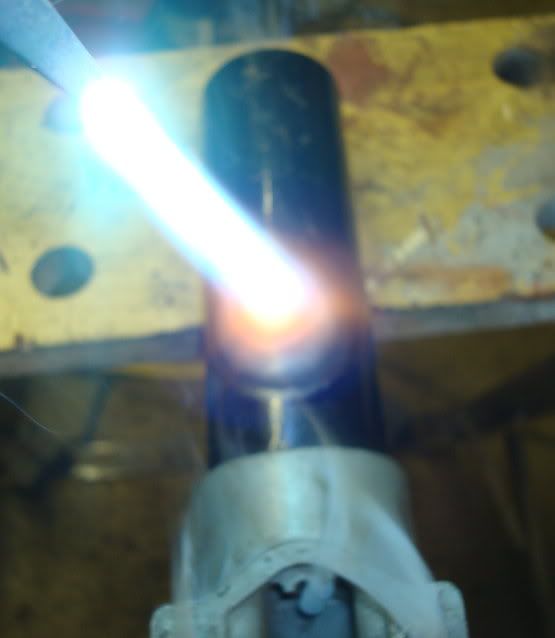 I did this quite a few times, and while it did move a bit, that was it and it wouldn't go any more. I ran a file over the base as it wasn't quite flat, and sort of favoured the front side, i9f you know what I mean. 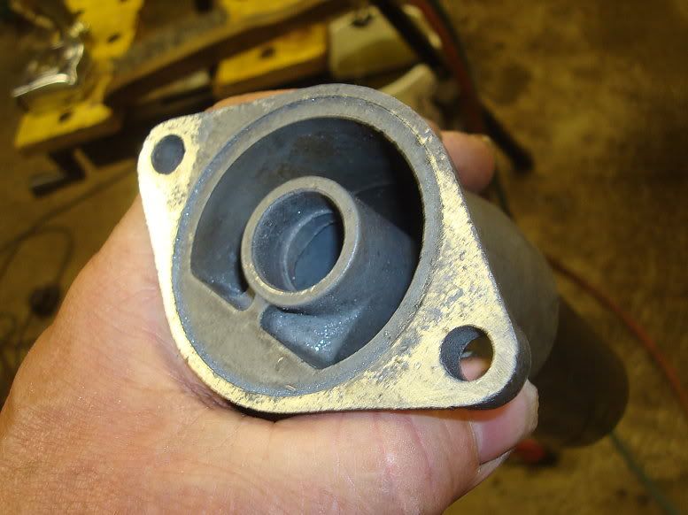 This was enough to just get it to clear, but it should really have more clearance than this. 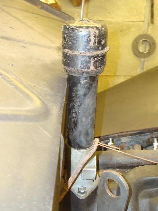 If I have the firewall insulation out at any time I might just heat up the firewall locally and put a little dent in it to give more clearance. That was a little bit of a diversion, due to getting the filler tube last Friday. As you will be aware, I tend to tackle the big job stoppers first, because without those things fixed, the project has no chance. Next job stopper was the radiator. It must have have frozen up with some water in the bottom, because the lower tank was all swollen up and the seam was split. 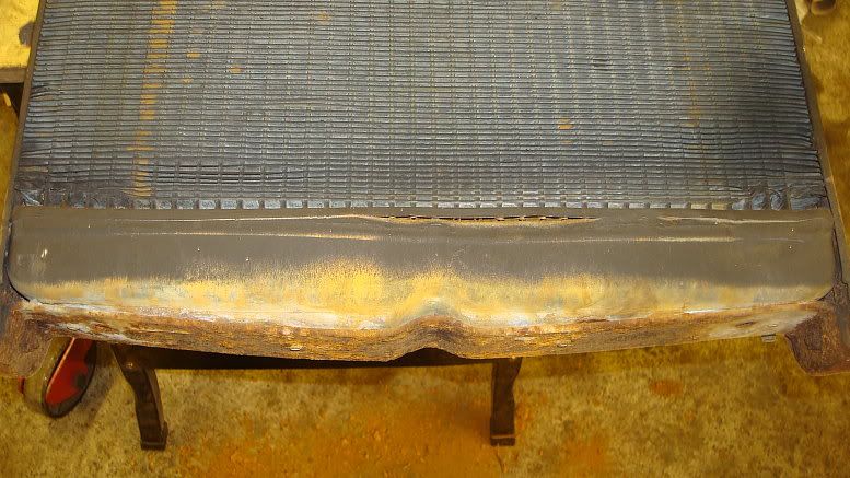 I started to dismantle it, and saw some copper rivets holding the bottom plate to the lower tank. I ground the heads off, and removed the plate. I had to cut through some screws at the side. 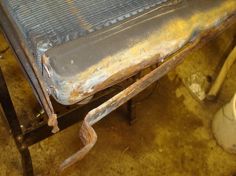 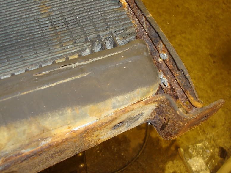 I set up a piece of 2x4 in the vice and knocked the tank into better shape. In this pic the left side has been bashed into shape, the right side is still bulging out. 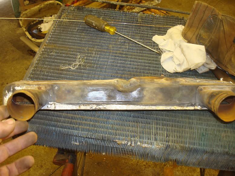 I then carried on straightening and cleaning and getting the parts ready for reassembly. I stopped taking pics at this point because it was difficult, and I had my hands full. Anyway, for now, here are the parts ready for final cleanup and reassembly. 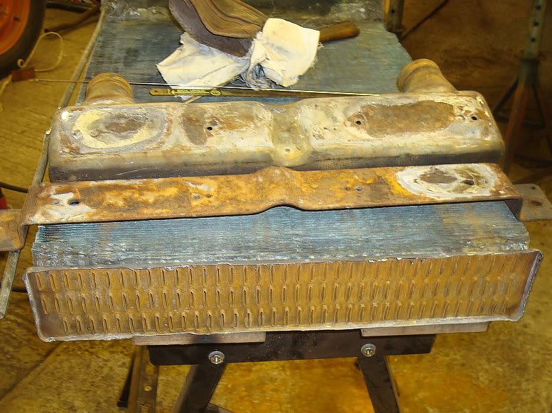 And as if it was in the blink of an eye, the bottom end all back together: 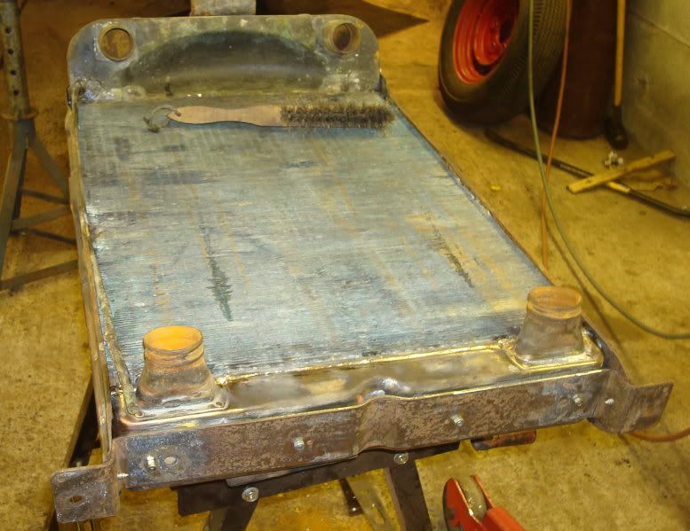 The side plates soldered bottom: 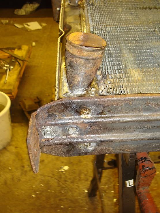 And top: 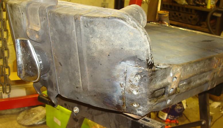 And the rad set back in place: 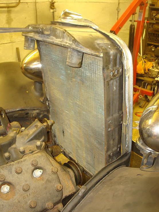 I reused the bottom hoses that were on it. They seem in good shape, nice and flexible, but not too soft, so I'll give them a go. Once the rad was back in I could drop the grille back in place. I seem to have some anomalies at the front end. The brackets on the rad do not fit very well to the grille. Some internet sleuthing tells me the brackets (well more like remnants of brackets) on the rad are 34 brackets. I don't have an answer to this, maybe the rad was replaced with a 34 rad at some point. (maybe recently). Other stuff going on on the side is I have ordered some reels of cable to do the wiring. and I don't know if it will work out but my scrappy is going to save me some exhaust systems and I'll cut them up to make an exhaust system. The guy I used to get all my pipe from has left the area so I'm sort of out on a limb now. And as usual, a parting shot showing the car as it sat last night: 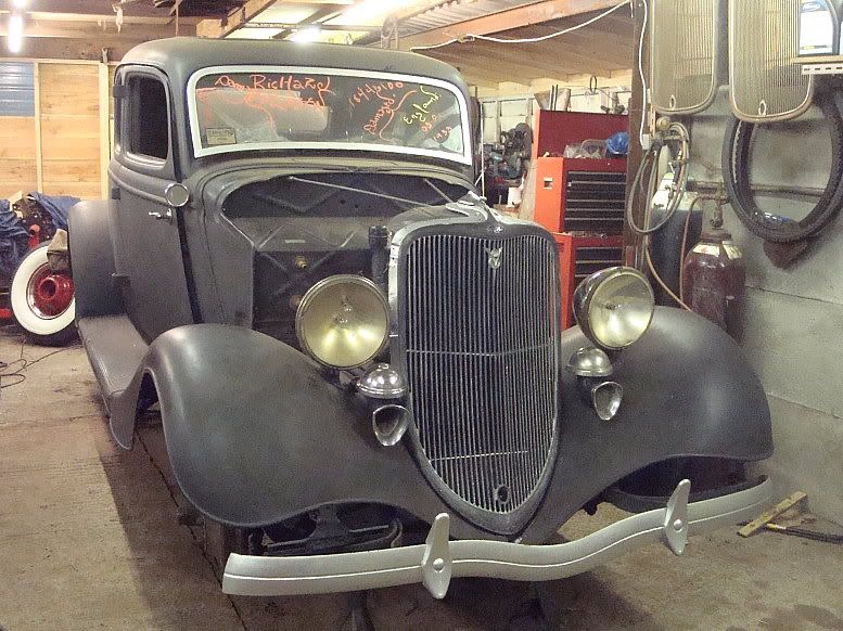 Sharp eyed ones will see a difference in the headlamps. The one on the drivers side has one bulb. the one on the pass side has two. I'm not sure, but I think the two bulb one is for a car without cowl lights, the extra bulb is the sidelight. The one with a single bulb is for a car with cowl lights. The cowl light is the side light. Funny thing is, my car has one cowl light, but that side has the lamp for a non cowl light car. Nothing adds up. Lots done, lots to do. Oh yeah, all the paperwork arrived today, import docs, US title, Customs duty paid form, etc. so that's another little loose end cleared up. Mart. |
|
|
|
|
07-17-2012, 02:43 PM
|
#38 |
|
Senior Member
Join Date: May 2010
Location: Solihull, England.
Posts: 8,756
|
6/4/12
Just some little bits and bobs to report. One problem I had was the unavailability of the brake pedal bush. This is a large thinwall bush, 1-3/16" bore and 1-1/4" od. Bob hadn't got one, and as far as I could tell no-one in the states had them either. As the bush was worn at either end, sort of on opposite sides, I decided to just bodge it up. I mixed up some two part epoxy and let it set in the worn areas. After letting it set for a day I carefully filed it out until the pedal slipped over the shaft. Not ideal, but hopefully should protect the pedal from further wear until the bushes become available again, if ever. When I heated and bent the pedals, I didn't have the engine and box in place. I soon realised a little bit of rework would be in order. 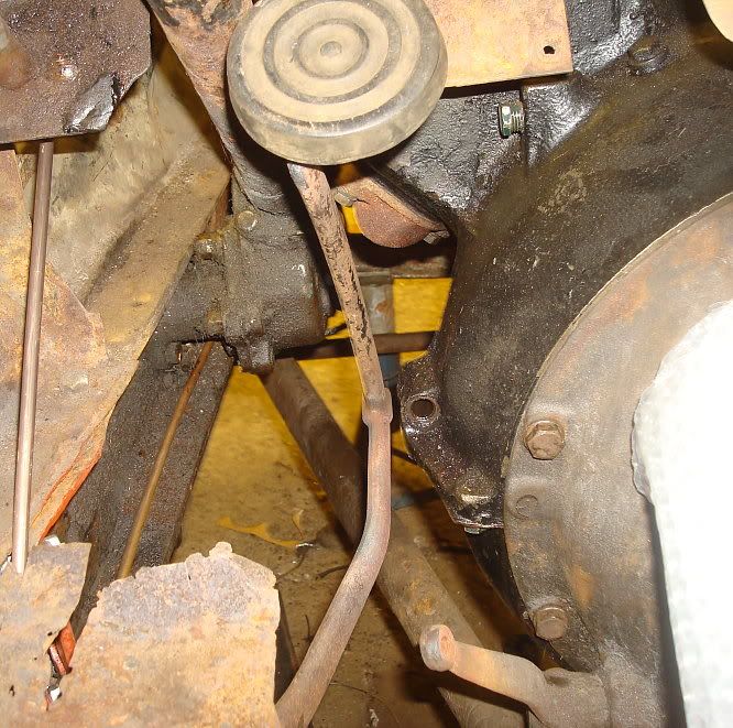 Had to heat the brake pedal to clear the bellhousing area at full stroke. Then had to get the arc running true and then bend the pedal mount bit to the right to clear the column. My oxy acetylene kit has proven absolutely invaluable on this whole build. Cleaned up and fitted the push rod parts with a new eyelet piece and found a problem. Couldn't get the cotter pin in. Here's the problem: 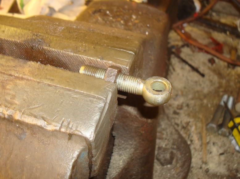 The threads go too far up towards the eye. Here's the fix: 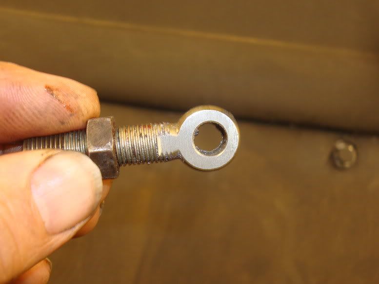 File the threads back to the same thickness as the eye. Here it is in situ: (a bit hard to get a good shot) 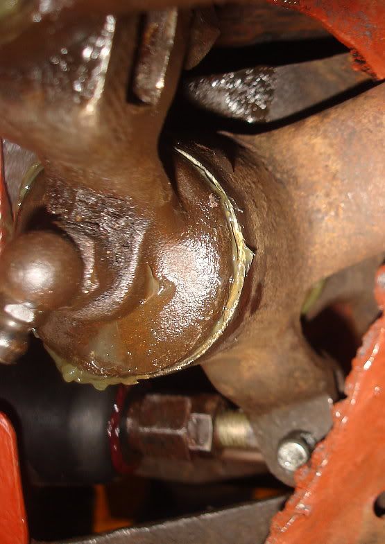 Just another example of the repro parts not quite working right. Put the clutch pedal and shaft in. This had been heated and bent to clear the floor and give good clearance to the fuel pipe. 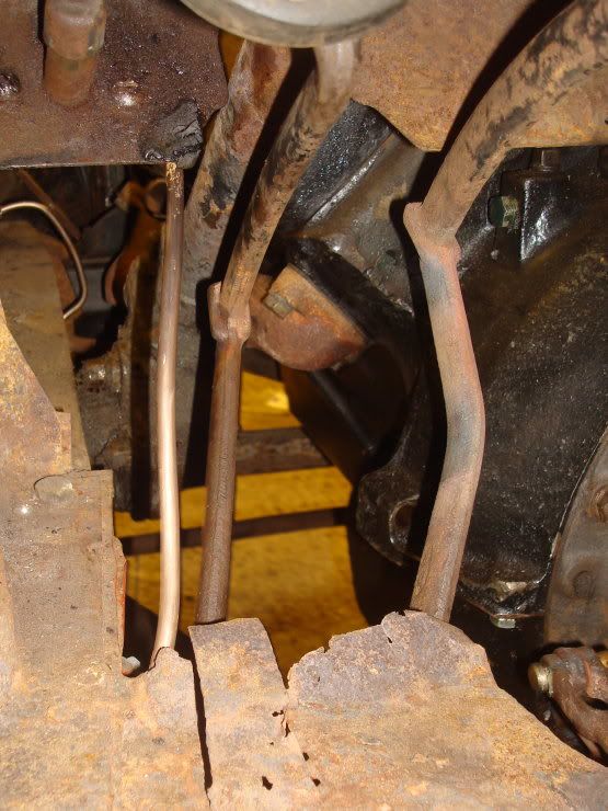 Heated and bent the clutch release lever to allow slightly better alignment, freed off the pushrod parts and straightened them, they had been quite severely bent. As I don't have a 39 release lever, there is still a compromise. I mounted the pedal end outboard of the fork part on the pedal shaft, instead of between. I used a long bolt with plain shank running right through all 3 parts. 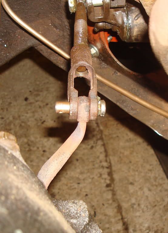 I sort of missed with the camera the bit I'm talking about is half off the top of the pic. So other than fitting some return springs and splitpins, the pedals are done and useable. In parallel to this I was starting to sort out the electrical side, trying to work out what I have, and what I need. I sourced some headlamp bulbs here in the UK thanks to Fil, and Lars has come up trumps with some usable reflectors for the headlamps. Thanks Lars. I ordered a load of wire, far more than I need, because at some time, I will need to wire the truck and the sedan too. Havn't started wiring yet, but hope to soon. Other than the pedals, I have been looking at the fuel pump and stand. I found a usable pushrod and tubular baffle and a fuel pump. I retrieved the inner tubular part from the 59A and after firstly trying a push rod from a French motor (was too long) I used the one out of the 59A. I had to straighten it as I had bent it when rolling the motor over. Ok, so how do you tell if your push rod is long enough and not too long? You mount the pump on the stand and leave the stand nuts loose. you turn the motor over until the fuel pump push rod at at it's maximum height. If the stand rises about 6mm off the manifold then the push rod will work ok. If it goes higher then keep pushing the stand down. if it meets the manifild ok then the length is also ok. If the stand won't meet the manifold then the rod is too long. You can tune the length of the rod for maximum if you use the mech fuel pump for racing. I looked on the internet for pictures showing the fuel pipe routing into the engine bay and layed my pipe in as best as I could, and hooked it up with the standard flexy pipe. I connected the fuel pump to the carb using a pipe I had used the last time I used this motor in Old Rusty. I put a little npt plug in the oil return hole in the fuel pump stand. Returning the oil in here is a problem if you have a lot of blow-by. Here's a pic: 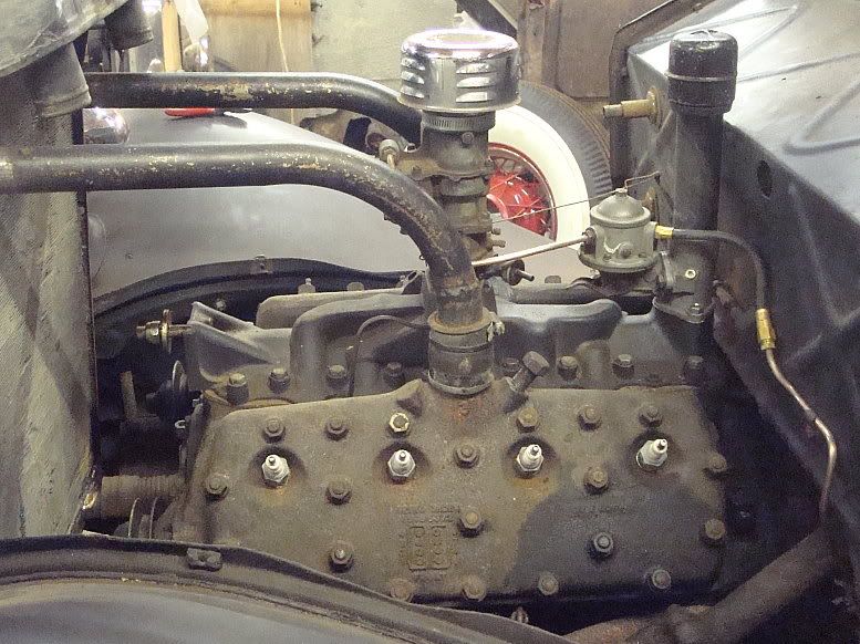 The pipes to the rad are the ones from Old Rusty, I just put them in there to get an idea of how I want to do the job. Anyway, a little step forward, and a few loose ends tied up. Have the rest of the week booked off, so I hope to keep knocking a few more little items off the list. Mart. |
|
|
|
|
07-17-2012, 02:45 PM
|
#39 |
|
Senior Member
Join Date: May 2010
Location: Solihull, England.
Posts: 8,756
|
6/8/12
Ok, this update will be a bit disjointed, because that's the way it has been. While not in real time, it will follow the order I did stuff. I booked the week off work so although I havn't been on it full time, I have managed to do more than normal. I started looking at the wiring. In a sort of ass backwards way. I knew I had the parts lined up for the headlights, so ran some wires to the headlights, and connected them to the old sockets. Luckily all the sockets were usable. The reflectors from Lars are on their way, and I have the bulbs now, so the headlights are "done" in my book, meaning I can stop worrying about them. 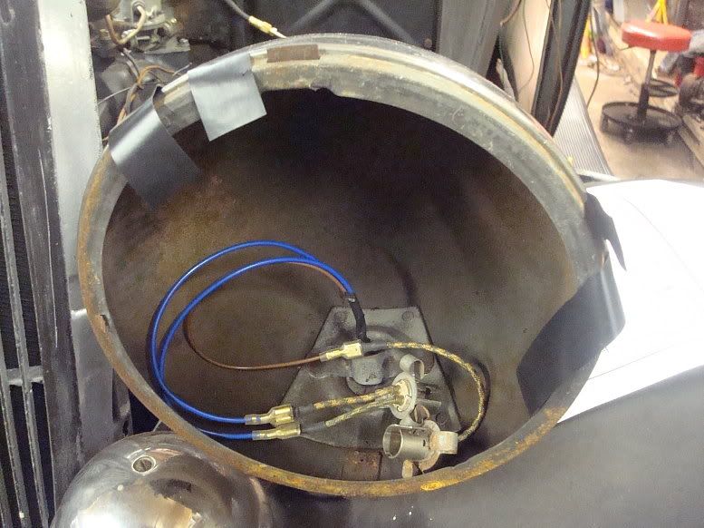 I ran some wires back along the car and up behind the dash, but didn't really have a proper route set out so I just left them long so I could work it out later. I did the same for the taillights. Removed them, replaced the socket in one of them, and spliced in new wires, ran up behind the dash like the headlights. 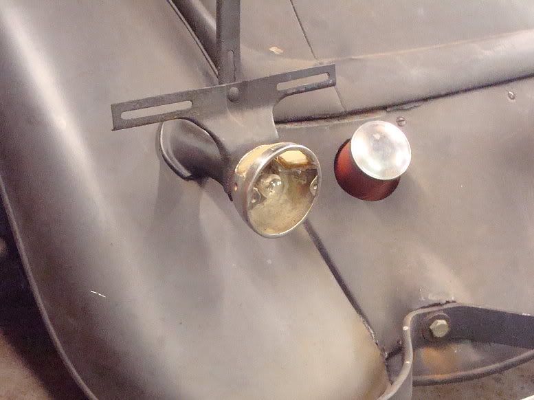 I ran the wires to the rear so I could use the brakes as indicators, and laid a wire in for the tank sender too. I removed the dip switch, cleaned it up and refitted it after checking the operation. I assumed it was stock but I now believe 33's didn't have a dip switch, the main / dip action was part of the light switch. I did the same for the headlamp switch (again not stock 33), and cleaned it all inside and reassembled it ready to go. I had to locate a couple of components. I saw that the regulator had been on the firewall, because there were three holes that matched it: 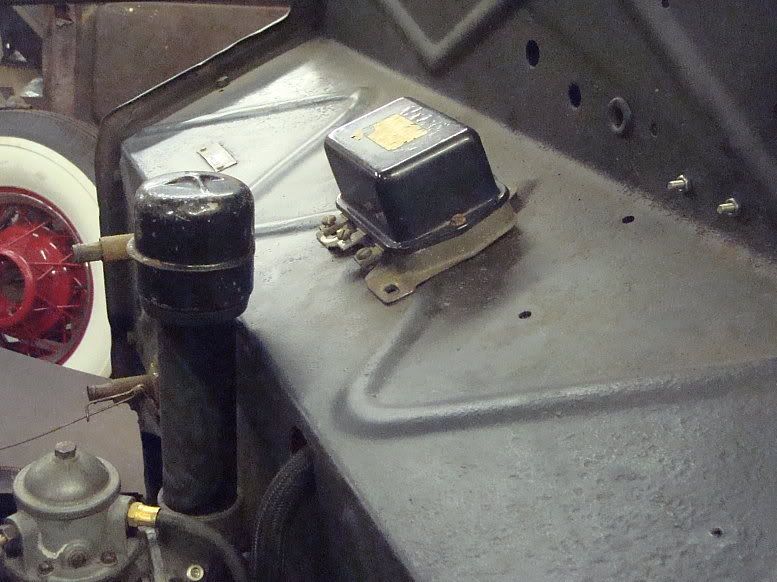 But I decide that looked a bit crap, and it was right by the oily breather so I located it inside the car, high up on the firewall, on the driver's side. 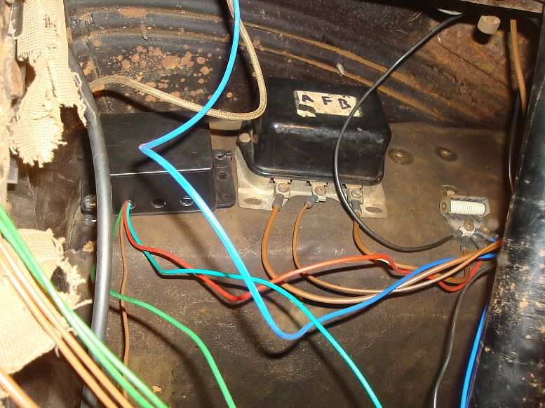 I also cleaned up the solenoid that was in a box in the car. I looked for a good place to mount it and decided to fit it down on the little floorboard extension, part of the stock 33 floor. 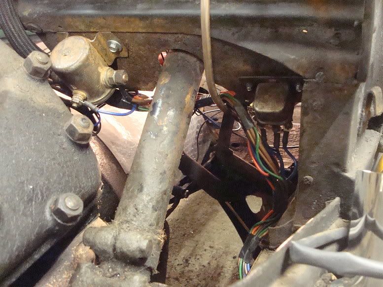 I put it down here, because it is a little out of sight, and the original 33 used a starter switch, foot operated, just a little further over. You can see the dipswitch also in this pic. I had looked online to see how the stockers are wired, and saw how the wiring went through a hole in the firewall. I decided to route all my wiring in the same way. I had looked at bringing it up the a-panel but discarded that for the more stock type setup. I had a short length of expanding braid type shielding so I threaded all the wires through that and fed everything through the hole in the bulkhead. 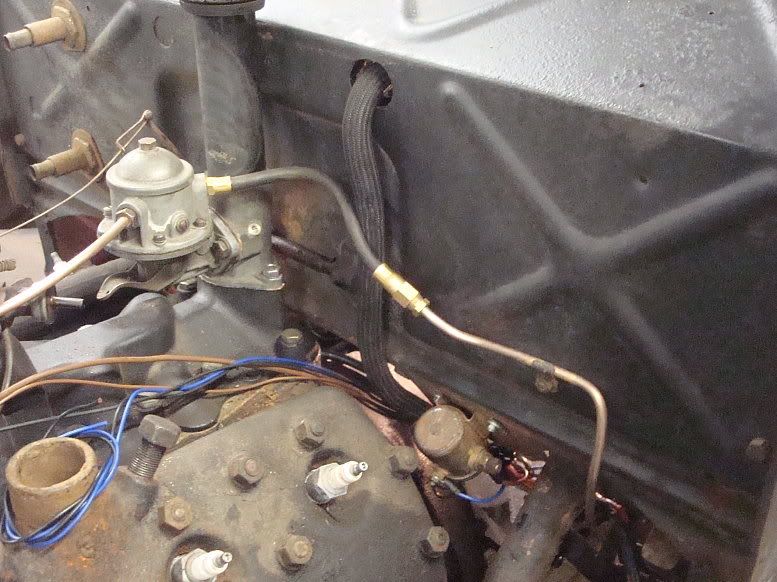 It's nice and low-key. I must admit I had to undo it about 5 times and keep rethreading more and more wires through it, as I remembered other stuff that needed a wire. While all this wiring was going on I had a little diversion. I wanted to get the windscreen out, and was pleasantly surprised that the regulator worked, and it wound out fully. 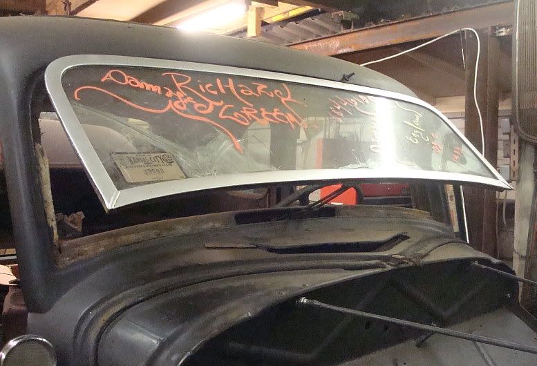 I decided to indo the top hinges, so I set about removing the header panel inside the car. I removed the panel, and hello, what's this? 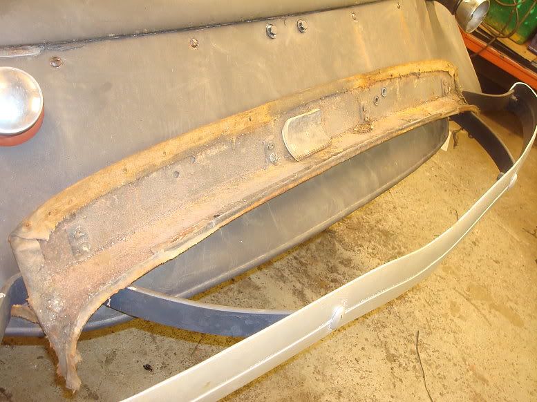 There was something tucked behind the header, must have been tucked in and then fell right in at some time. It was a little address book, you know, a "little black book": 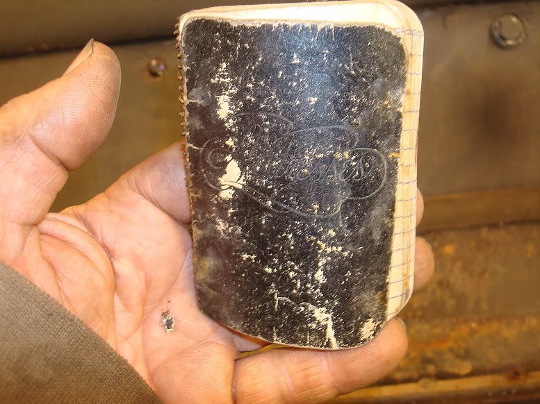 There are 10 or 12 pages filled with names and addresses, mostly female names, as it happens: 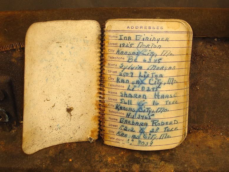 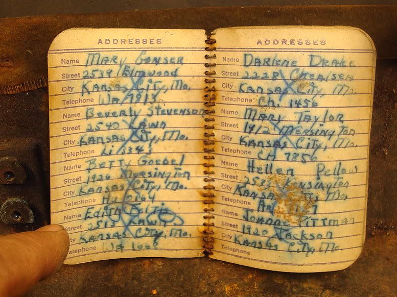 And so on and so on. A lot of the names have a big X through them, quite what the significance of that is, I'm not sure. A lot of these people may still be very much alive although getting on in years now, but this is a closed board, right? So I hope I'm not compromising anyones privacy. Still fascinating, though. Anyway, back to the sparky stuff. Once the major components were in place, it's quite easy to start laying in and connecting up the wires. I like wiring, but don't do it often enough to get it looking really tidy. It normally works ok though. To run flashing brake lights you need a special relay setup. This uses two double pole relays. I used to make up these units and sell them, but I did this one a bit different as I could do it specific for this car and not sort of universal as the others. Two relays, taped together, with a flasher unit taped on top: 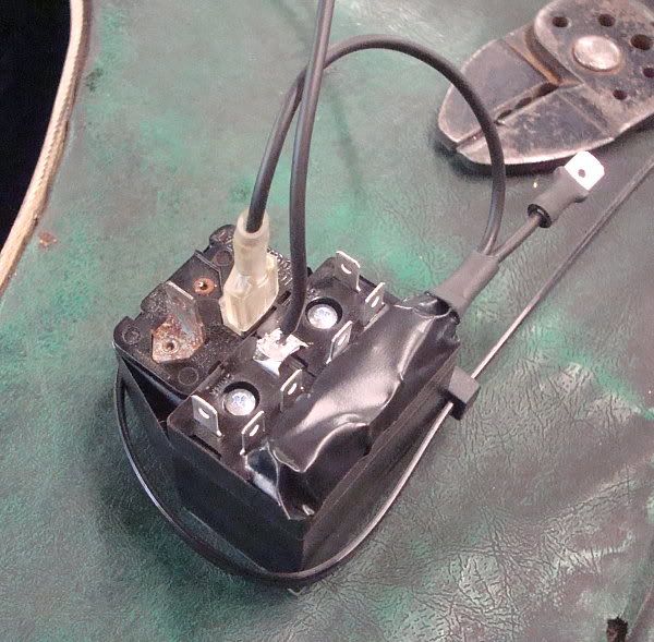 The bank of 4 connectors are for the 4 indicators, the two others are for the left and roght input. I am using a simple on-off-on toggle switch, nice and simple. And here it is with wires all connected, just cable tied to the (unused) ballast on the original fuse/ballast unit. 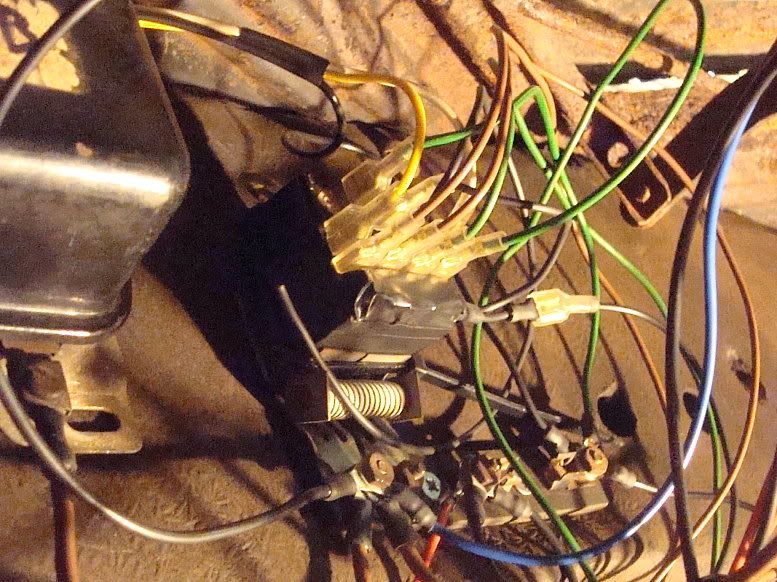 It's still a bit messy, but there are now a lot of wires under the dash. I used the posts on the fuse board to provide three feeds. First is a Bat post, wired straight from the bat terminal on the solenoid This feed passes through the ammeter as it should show whether the juice is flowing from or to the battery. This feeds anything that needs a direct supply.. Lights, ignition switch, regulator bat post etc. Second is an unfused ignition live terminal. This feeds the ignition, or in my case the ignition module, because I'm running an electronic amplifier on this one. (I used to make these too, funny enough). Third is a fused ignition on terminal, for brake switch, indicators, etc. Nice and simple. Keep it simple. It's the only way. Couple more things. I bought a 6V flathead generator and a 12V Y block generator last year, and had put together a 12V flathead unit from the parts. I bolted this in place, and was able to run the wires to it. 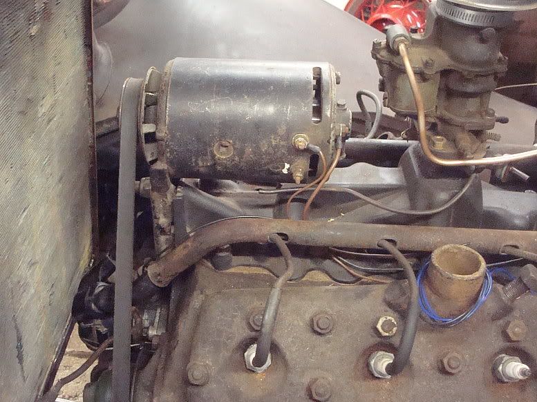 I still needed a distributor, so looked at the one that came on the car. It was a bit crusty: 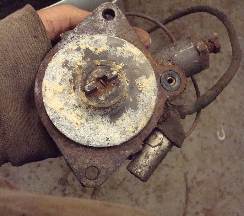 Interesting to see the original feed wire, with it's cloth braid protector and the original capacitor with a rubber shield on the live bit. It was crusty, but when I gave it a quick wire brush it cleaned up easy. I popped the cap and it looked ok inside: 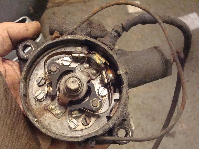 I decided to use it. I stripped it down and the advance mechanism was free, but the cam was tight on the shaft. I oiled it and got it freed off. I cleaned it up and greased it and put the unit back together. I cleaned the points and they looked to be in good condition, and as they were original Ford parts I thought they would probably work better than the modern repo stuff. 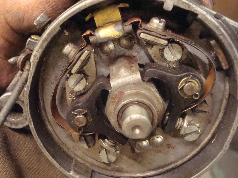 You can just make the F M Co script on the base plates. 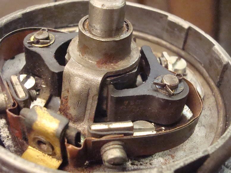 and the Ford USA on the points. Now, heres where I may have overstepped the mark on the "use the old stuff" idea. I cleaned up the cap and leads and put them on as well, with the plug wire tubes exactly as removed from the 59A. It may work, it may not. I'm sort of curious to see if it will work, so I'll give the old stuff a go first. The distributor in place: 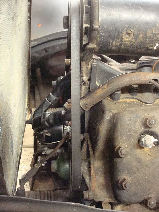 And the leads of dodginess: 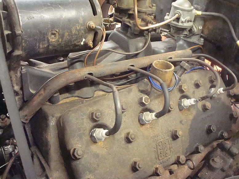 You may have noticed the fan belt has also appeared as if by magic. I couldn't fit it with the engine sitting where it is. I believe the cranks were shorter on the earlier motors. I found it was easier to undo the u-bolts than jacking up the engine. With the u-bolts out of the way the belt went on no problem. Well that's it all up to date for now. Still a bit of wiring to do, and a lot of tidying of the wiring to do. Sort of need to take stock now, and start knocking off all the other little jobs that need doing. Mart. |
|
|
|
|
07-17-2012, 02:52 PM
|
#40 |
|
Senior Member
Join Date: May 2010
Location: Solihull, England.
Posts: 8,756
|
I decided to push right on through - not that many posts left..
Mid June to Mid July.. Mart. ================================================== == 6/14/12 Blinkin' Lights! I had a problem. I want to run flashing indicator lights. I had some little Butlers sidelights and was going to use those as my flashers. I set them up down low behind the bumper, but wasn't that keen, then set one up on the cowl and couldn't decide. I asked in a thread on the Meltdown forum in the UK what people preferred, and the answers sort of told me what I was thinking but didn't want to admit: They both were a bit crap. But one suggestion, "Make the side lights flash and avoid both" set me thinking, and sparked an idea. The reflectors had arrived from Sweden (Thanks Lars) so I had the headlamps all wired up. He also sent the sockets for the bulbs, so I had a spare pair of twin filament sockets, which bayonet into the same holes as the single filament sidelight sockets in the reflectors. So the idea is to use twin filament bulbs as sidelight / indicator within the headlamp. this gives a 5Watt side light and a 21Watt flasher. I rigged it up and tried it and I think it works pretty well, and is a better, cleaner solution than either of the first proposals. Here's a piccy show and tell: Sidelight brackets made from chunks cut from the Mercury frame: 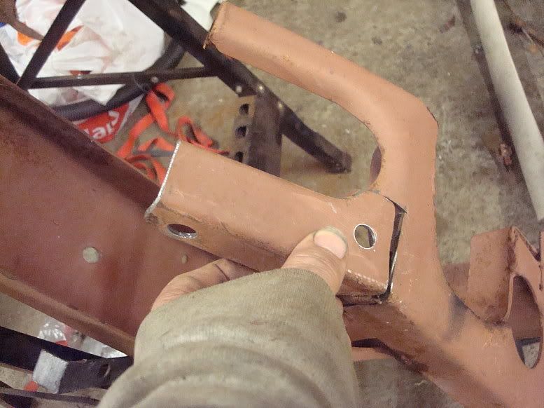 Both Butler sidelamps fitted: 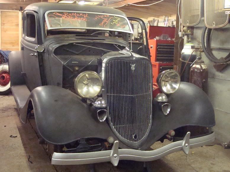 Wasn't too convinced, as the front is already a bit cluttered with the twin horns, and the lamps are partially obscured by the overriders. Tried one on the cowl (My car had one incorrect cowl lamp one side and an aeriel that doesn't work on the other):  Then tried to decide between either one, and asked on the Meltdown forum. 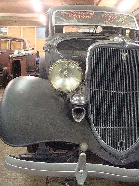 You can see both in this picture. And here is what I went with: Standard reflector with single pin holder for the sidelight. 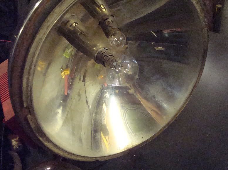 Fitted with a second twin filament bulb holder, same as the headlamp. 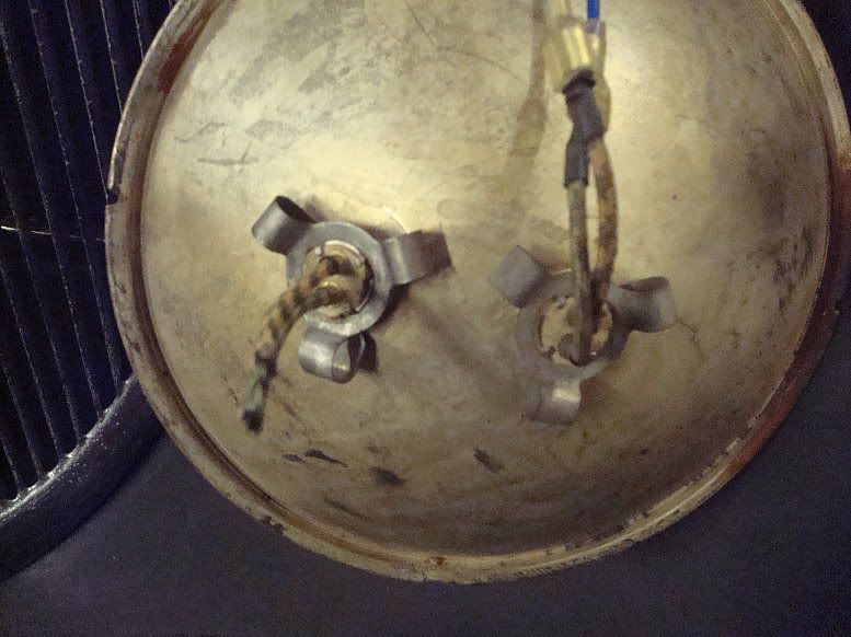 And the 5W / 21W bulb in place - it just clears the headlamp bulb. 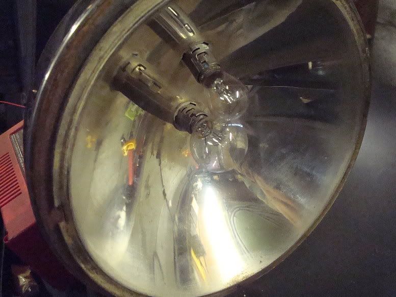 I had to unwrap the wires and put in a 4th wire: 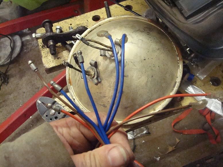 And a tip: If you want to thread 4 bullet connectors down a tube you have to stagger them. (You can see where I mis-crimped one of the bullets in this shot) 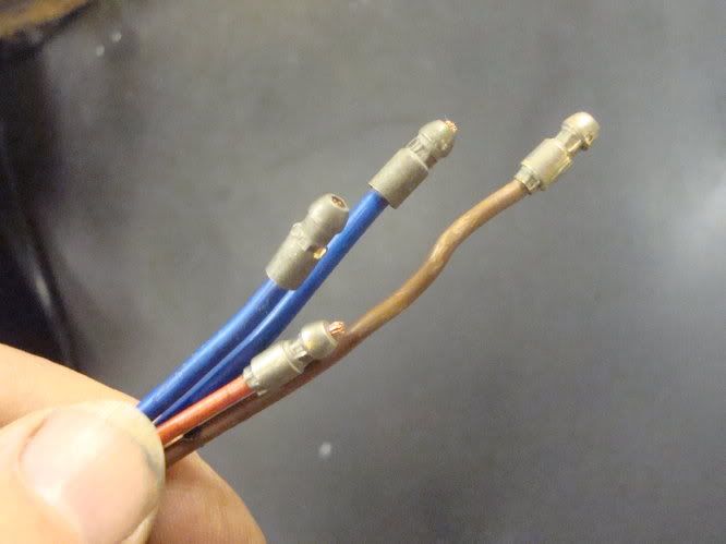 I learnt this from a 100E indicator switch, which has the wires down the centre of the column. I hastily made a few connections and: (Click on the picture) 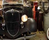 So I can now ditch the Butlers, lose the cowl lamp and now move on to other stuff. Mart. ================================================== 6/16/12 Thanks again for all the feedback. I had another thinking session and came up with hopefully a final iteration. Ok, I had been browsing a lot of 33/34 pics and realised only the resto cars tend to run the horns. One of my horns was a bit out of alignment and missing the mesh so I pulled it. 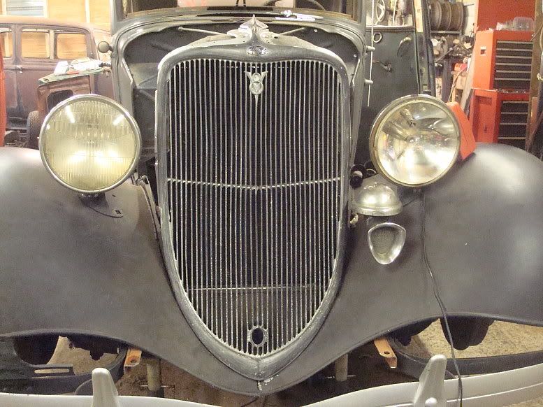 I made up a little bracket and bolted the butlers lamp on. 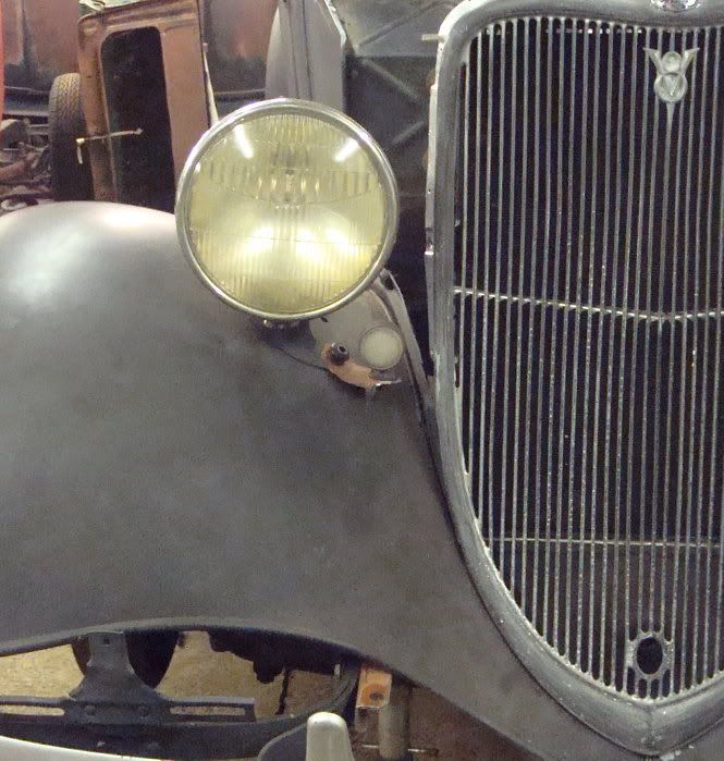 And: 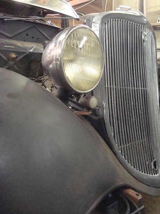 Of all the proposals, I like this the best. I can get a small 23W bulb in the butlers unit and I'm pretty sure there is an orange version available. Backstepping a little, With the previous setup I hooked up a battery to get enough oomph to power the lights and indicators at the same time, and as Lars had indicated (geddit?) it would be confusing. I could use an amber bulb, but then would be stuck for a sidelight, so I ended up rethinking it again. So I'm pretty sure I'm going to give this setup a go. With a little touching up with matt black paint thay will sort of blend in, but show up when illuminated. No Henry Ford sheetmetal has been harmed in this experiment. The brackets are made from metal cut from a Mercury frame. Hardcore! Mart. ================================================== = 6/16/12 Thanks Mike, I'm glad you're enjoying following along. I said right up front it will be warts and all, and it really is in real time, so the fubars and blind alleys are all there to see. 730 Had a couple of hours in the garage this evening, and finished off the indicator installation. The pics below are video's you click on 'em to make 'em run. Here's the result: Right: 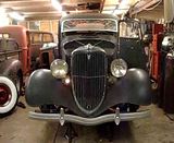 Left: 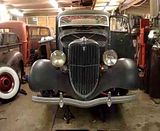 And right with the lights on. Please excuse the rambling. 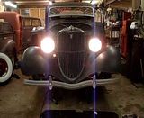 In reality the headlights are nowhere near as bright as the camera makes them out to be. I might try a different flasher unit to see if the light will stay on longer, and also might try some amber or orange bulbs. I thinks the car looks slightly more badass without the horns. A bit of matt blackery will visually diminish the new lights and bracketry. Here we can run white indicators at the front, and red on the back if the car is older than (something like) 1966. But legally the indicator is supposed to be within 400mm of the edge of the car, but hey ho you can't have everything, can you? We're not allowed to run amber sidelights, which causes some problems when importing later Amurrican cars into the UK. I also mounted the coil using the original 59A bracket. Wiring that in and making a new HT king lead will be the next jobs now the front indicators are finally settled. Mart. |
|
|
|
|
«
Previous Thread
|
Next Thread
»
 Linear Mode

|
|

| Sponsored Links (Register now to hide all advertisements) |
|
|
All times are GMT -5. The time now is 04:45 AM.