|
|||||||


| Sponsored Links (Register now to hide all advertisements) |
|
|
 |

|
Thread Tools | Display Modes |
|
|
 07-05-2025, 10:35 PM
|
#1 |
|
Senior Member

Join Date: Aug 2023
Location: Southern California
Posts: 177
|
Hey all! Okay, so this might have to be a multi-part post as I'm not sure how long/how many photos I can post in one single post. So, bear with me as I showcase this really fun project I did a few months ago. I thought I'd share what I did here to inspire others to, perhaps, do something similar. This will be a long read with a lot of modern technical jargon, so hopefully you read along! I'm going to put the image captions above the images.
As I slooowly restore my 1940 Ford Deluxe Fordor, I've worked on smaller projects when I can and to take a break from being frustrated on the Fordor! My Fordor came with the original Zenith radio. While it powered on, including the lights, the speaker was blown/dead, and the capacitors/tubes were all fried. Turning it on only made a humming noise, but nothing else. I even tried to attach the antenna, but nothing worked. It's dead. Now, I could have gotten new tubes/capacitors (no guarantee that would fix it) or even just had the radio fixed (expensive). Furthermore, here in SoCal, there are really not many AM stations left I'd want to listen to. Mostly just talk radio and foreign language stations. So, I originally thought I'd just change the system over to a modern Bluetooth system and just send 1940s music to the radio that way. I've done that to 1940s radios that were beyond repair electronically. So, that was my plan at first (but majorly changed)... And thus the idea was formed. So, let's go through the first few steps, figuring out how to do this to the radio itself. Here's a look inside a 1940 Zenith radio. Yikes. Even though I love tinkering with electronics, even I opened this up... paused, and audibly said aloud 'NOPE!' and closed it back up. This is when I made the decision to go the 'modern conversion' route. 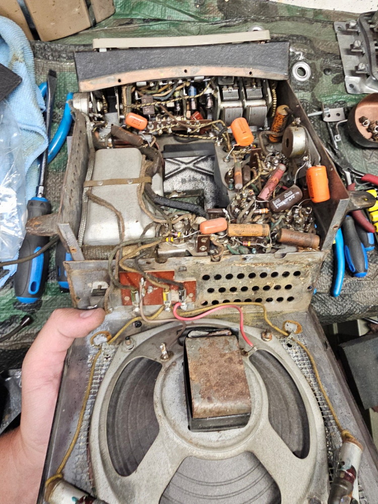 Now, I didn't want to harm my original radio. Doing this process means gutting the inside so you can fit the modern electronics. While many people wouldn't bat an eye, I just couldn't do that to my original radio. So, I went on the hunt for another one. And I scored an incredible deal on one at a Model T swap meet event for $10! This $10 one turned out to have a blown speaker as well, and the inside electronics were in unrecoverable condition. The photo below shows the $10 one (left with Bob Drake rubber pad) and my original on right. 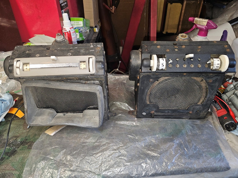 Looking at this spare one, it actually came with some neat markings. Inside the back cover are the original paper patent numbers and tube layout guide. I made sure to keep those on there. The Drake rubber boot, though, isn’t in the best of shape (and stiff), so I'm going to replace it with a new repro. 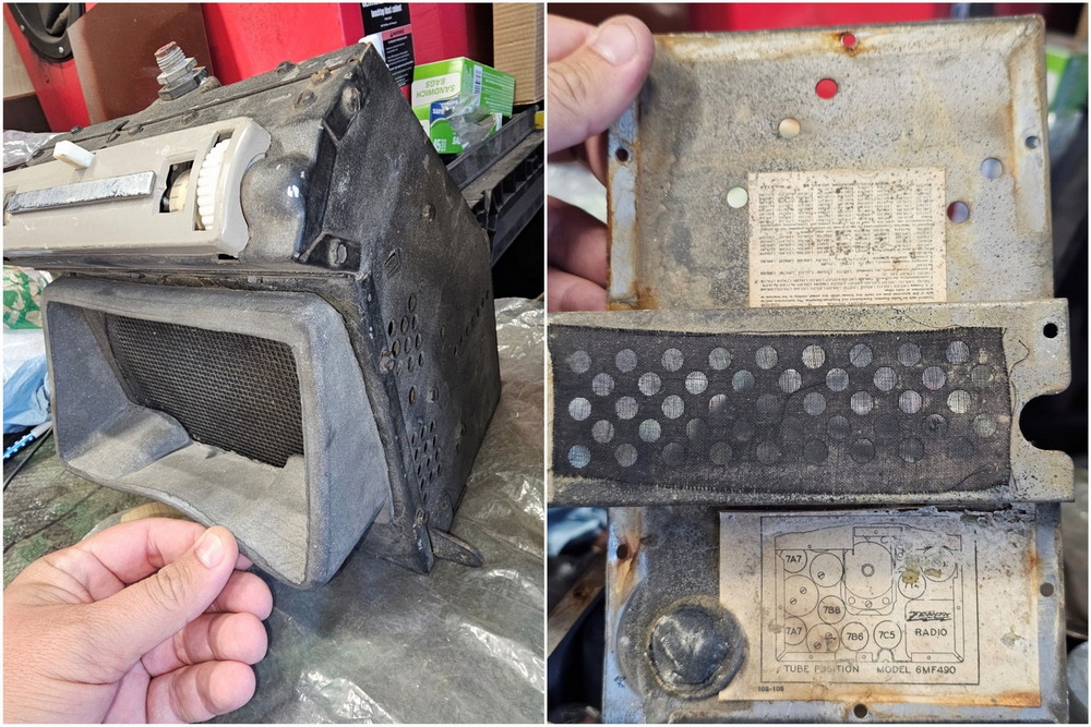 Here’s a look inside at all the tubes in the sapre. There’s so many crammed in there! That wire mess is on the other side. I tested all the tubes, and they were all shot, some even cracked and the terminals on the radio body itself corroded/rusted/cracked. So, I don’t feel as bad about tearing this all out of there. I would need to get rid of EVERYTHING inside the radio you see here to make this idea I had come to life. 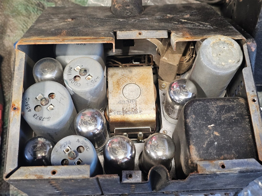 On the speaker side of the spare radio, I tested it and the light bulbs. As you can see, one of the lights still worked. The speaker was blown just like my original, and is not functional. So that would need to be replaced. I knew I could find a replacement speaker the same size on Amazon or eBay. 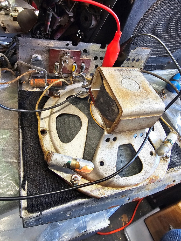 So I got to work. Even though it was a busted spare, it was still difficult for me to rip everything out and destroy the interior. I really don’t like destroying original things, so I had to keep reminding myself that this is bringing new life to this otherwise junked radio. It took HOURS for me to rip out everything; there were so many things. What you can’t see is the massive pile of wires, parts, etc to the right. 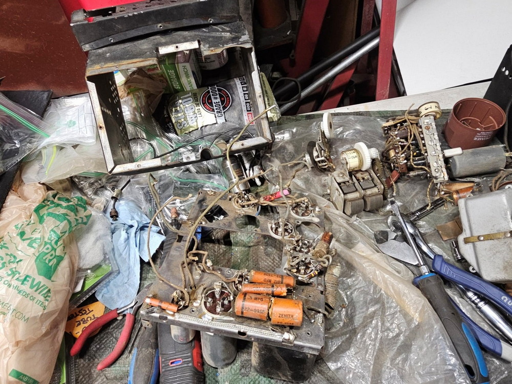 Finally, getting it almost down to the main plate. This sits in the center of the radio and holds the tubes on one side, and all the wires/capacitors/resistors/etc in the other. I realized I could actually use this bracket with the new electronics. 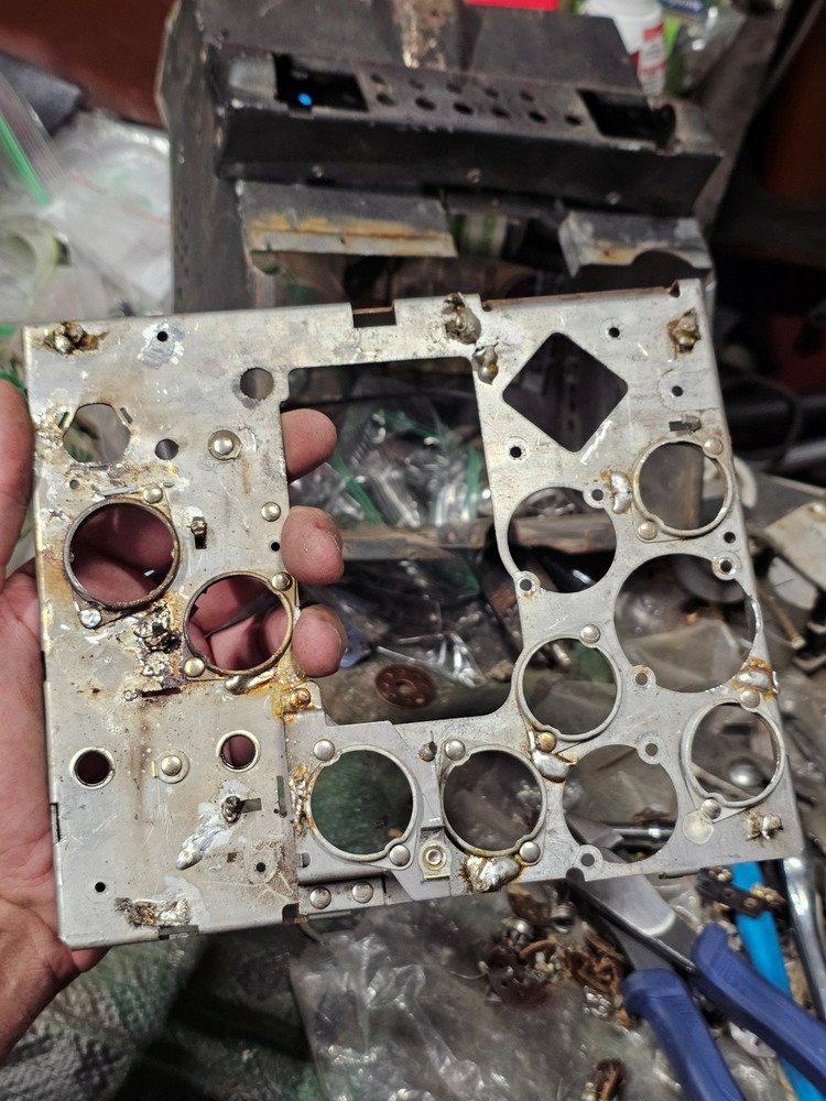 Here’s the original station tuning dial. It’s the same style as a larger tabletop radio, but just smaller. I was already trying to figure out how I could use this dial in some way, and ideas were forming... 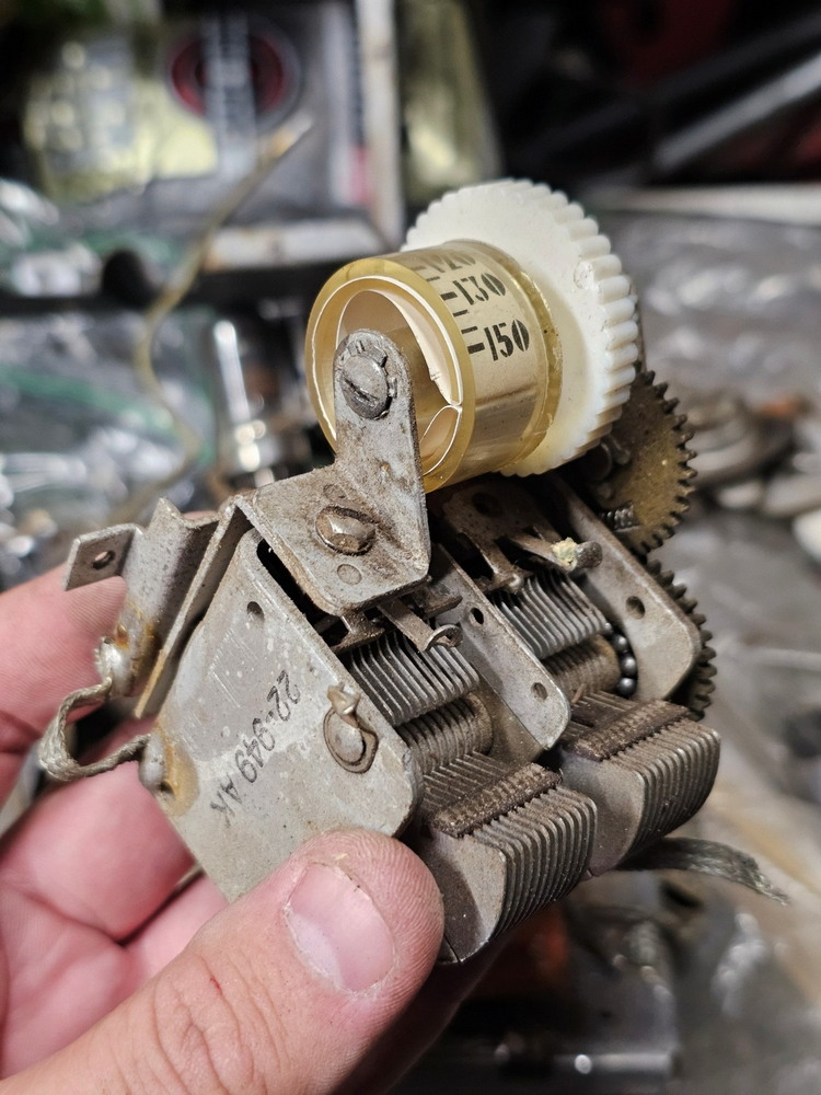 Here’s the mechanism for changing the preset stations. It’s impressive engineering. You press the button on the right (just out of frame), and that rotates the shaft one partial turn. That moves those metal tabs in a way that only makes one contact at a time. That contact that’s being made then feeds to a different bracket that has a bunch of screws that tighten/loosen a wire. Each of those screws are turned an exact amount by the Ford dealer to the ‘local AM stations’. Crazy right? So that’s how it can switch between the different preset stations. Again, I’m looking at this wondering… can I somehow utilize this push button to change something? 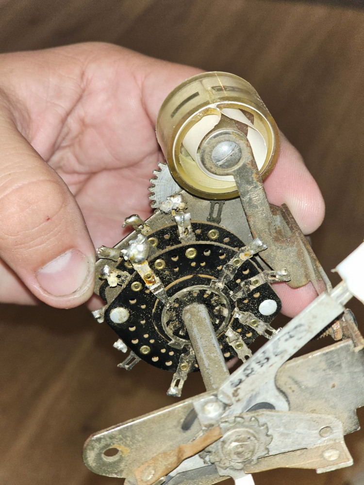 Looking at the other side of this station changer bracket, you can see the three gears that turn the station indicator dial. You can also see the push button in the back. 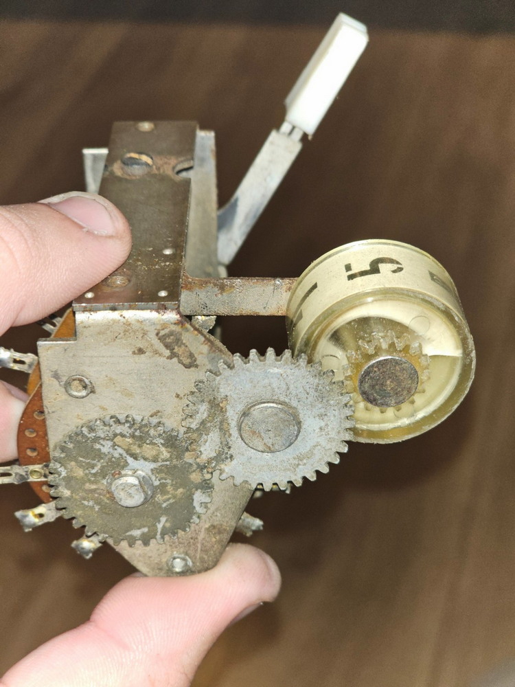 One thing I wanted to note was that I found original inspection markings from the Zenith workers who were putting the radio together. So cool! 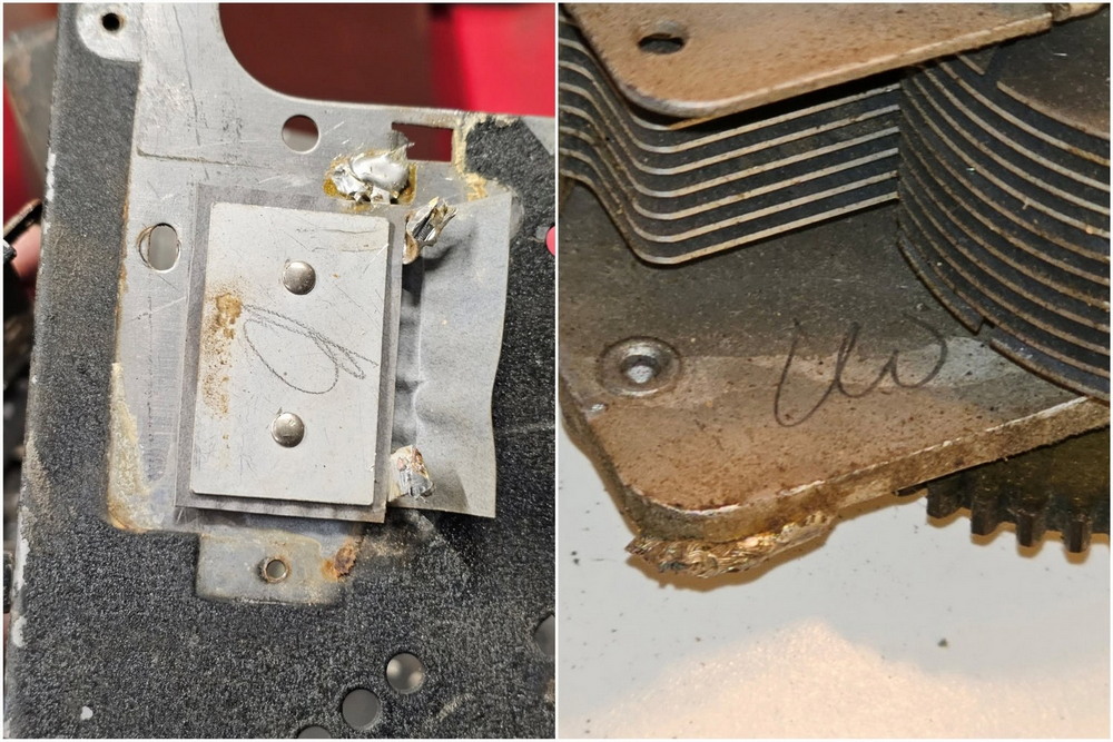 Going back to that middle plate, after cleaning it up, removing all the last bits, including soldering that was done to it… Here’s what I was left with. I figured I could use a lot of the holes to mount things. But that presents an issue since it’s metal. Mounting a bluethooth control board directly to the metal will instantly short it out. So I would need to figure out a way to mount them ‘outwards’ from the metal so they don’t touch. 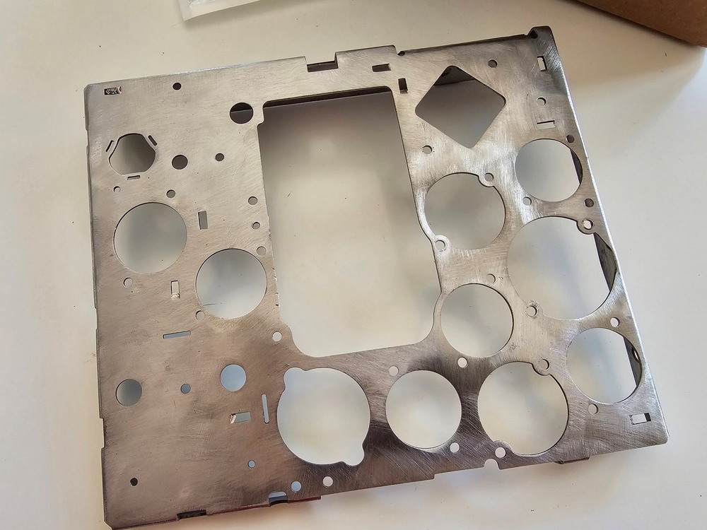 And here are the four basic brackets I wanted to keep. TOP L to R: The volume dial, the pre-set station changer button/indicator, and the manual station dialer. At the bottom is the main bracket with the screws for the preset stations that the dealer would turn. I’m only keeping that bracket as it is visible on the top of the radio, but (at the time), I didn’t have any practical use for it or the push button other than cosmetically making it ‘seem’ like the radio is all there. 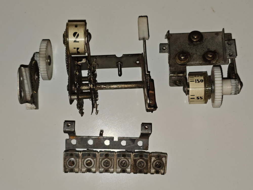 Now, I got to work cleaning the inside of the radio housing. 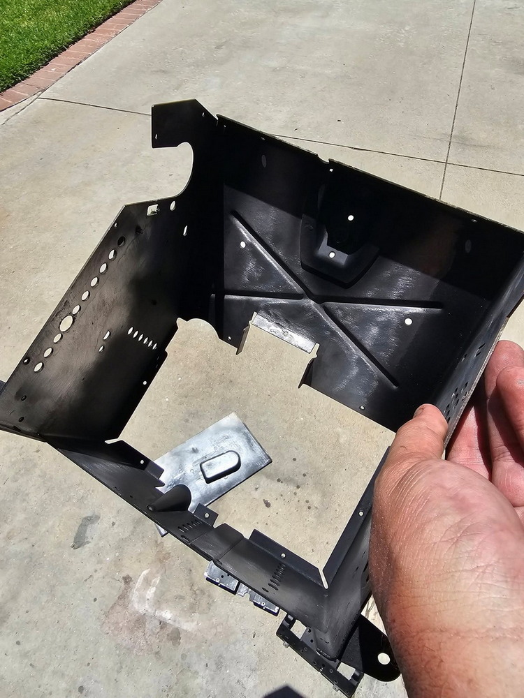 Then came the time to repaint the radio! I had to mask EVERY HOLE that goes inside the radio, as I didn’t want overspray inside to ruin the original paper guides. And I couldn’t mask those guides with tape as they’d rip off. 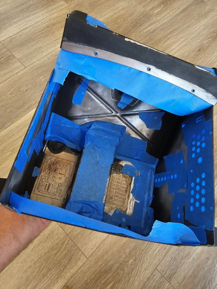 Below shows the radio masked, lightly sanded to fix any nicks or marks, and ready for paint. I decided to use a wrinkle paint on a hot day to simulate the original crackle look. Won’t be exactly the same, but close enough considering it sits behind the dash. 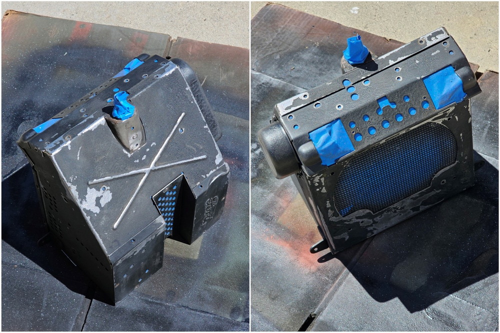 And here it looks after painting and letting it bake in the hot sun. Almost appears brand new! Now that the radio was cosmetically done, it was time to start working on the inside electronics, and about this time, I came up with an idea to take it beyond a modern Bluetooth radio...  I'm going to take a pause here and submit this post. As soon as I get more time this evening, I'll continue with how this went from a simple Bluetooth radio into a self-contained 1940s radio station.
__________________
1940 Ford DeLuxe Fordor Sedan 1944 GPW Jeep Last edited by WarbirdPhotog; 07-06-2025 at 03:54 AM. |

|

|
|
07-06-2025, 02:31 AM
|
#2 |
|
Senior Member
Join Date: Aug 2023
Location: Southern California
Posts: 177
|
Continuing... After some time working on the radio and switching to the electronic components, I realized that I didn't want to have to connect my phone every time via Bluetooth. And I wanted to be able to control the volume from the radio itself rather than the phone. So I had a thought... what if I could build a self-contained 1940s radio station 'generator' within the Zenith radio?
*** A lot of technical jargon in this one for those who want to try this out, so bear with me. If you want to skip past the real in-depth technical talk, just skip to the first image. *** To make this radio station generator work, it would need to:
So I got to work thinking of how I could do this, formulating different ways to try and accomplish this, and I came upon a solution: what if I put a microcomputer inside the radio that could use MP3s in various folders on some sort of memory card (like a MicroSD card that you might use in your phone), and the various radio dials/button will interface with the micro computer? I went to work to research the possibility of doing something like this, and slowly, I was able to piece together a plan. And soon my idea started to look like it could be a reality. So here's how I envisioned it would work.
The big problem was... how can I power the Arduino? It needs a 5-volt negative ground system to function. My Fordor has the original 6-volt positive ground. That would mean that I not only need a 6-volt to 5-volt reducer, but I would also need to reverse the polarity for the Arduino. That turned out to be a huge task. So, below is my first concept I built to use as a guide for the entire setup. It looks like a lot, but it's actually relatively simple. The hardest part would be to find everything I need to reverse the polarity for the Arduino.  So, I ordered the parts, all from Amazon. The speaker is brand new, but a perfect fit on the vintage radio! Its also really loud. Then the Arduino Nano (middle left), the MP3 MicroSD card reader (middle on the orange foam), two rotational emulators, the tiny push button emulator, and the AMP board. It turns out that I wouldn't need the AMP board because the DFPlayer MP3 player board produced an audio signal loud enough for the speaker.  I decided to put together, program, and test everything outside the radio itself, as it would be easier, and to make sure this was all going to work. So I got a test board that allows you to put temporary wires to power everything. It powers the board with the exact power it needs, so no need to worry about the polarity reversing yet.  I hooked it all up; this was my test environment. And I got it to all power up and show up as functional. But the Arduino is just a blank computer. I would need to program it with my radio station idea. So I got to work. Hooking it up to my laptop, I started to write my own radio station generator program. I was able to get a basic system going pretty quickly where I could play 1940s music I had on MP3s loaded onto the microSD card, change the volume with one of the rotational emulators, skip tracks with the push button emulator, and change stations (folders) with the other rotational emulator. But that was just the start.  The speaker worked great, and nearly fit perfectly including using the same screw holes on the radio body as the original speaker! The only modification I would need to do is trip a little of the metal housing off the top. You can see in the photo below that the speaker slightly rises up beyond the lip of the front speaker grille panel of the radio body. But the fact that the screw holes lined up otherwise was pretty awesome.  So, with the initial test a success and I continued testing it, it was time to start to figure out how to mount the system inside the radio itself. Using the existing screw holes, I could mount at least one hole on each board, but I would need to drill additional holes. And I still needed to figure out how to mount these boards away from the metal, since they would be 5 volts negative ground if they touch the metal, which would be 6 volts positive ground that runs through the radio body, it would ruin everything and possibly even cause issues with the power system in the car.  I came up with a simple solution and found out it already existed nylon screws and extenders! Made for this very reason to keep electrical boards away from motherboards and other things that could short them out. Amazon had a set of different sized extenders, screws, lock washers, washers, and nuts all non-conductive nylon based! Score! Below, you can see the board lifted up away from the metal plate.  So heres the Arduino nano microcomputer mounted to the metal plate. Im using whats called a breakout board with the Arduino that makes life simpler being able to use screw down locks for the wires rather than having to solder them directly to the Arduino. Makes replacing the wires easier as well if something breaks.  So, in the photo below, we have the Arduino nano microcomputer (green arrow) and the microSD card DFPlayer MP3 player board (yellow arrow). Thats great and all, but I still needed to figure out the biggest headache how can I convert 6v positive ground to 5v negative ground? So, after spending a week researching, I bought a bunch of 5v to 12v converters that, supposedly, can change polarity. Of the three I got, only one (red arrow) worked. So great, now I have 12 volt negative ground, but now I need to reduce the voltage from 12v down to 5v for the Arduino. So, I bought several 12v to 5v reducers. The one (orange arrow) I was really hopeful to work but it wouldnt take the 12v at all for some reason and just wouldn't function at all. UGH.  Again, I tried four different 12v to 5v reducers, only one worked (red arrow) I was getting a steady stream of 5v negative ground now to power the Arduino and MP3 player! Hooray! It only took seven tries and waiting for various Amazon shipments throughout the week! Heres the entire wiring setup for everything. I used the grey click connectors also for ease of being able to replace/repair any wires that might have issues. Also easier to troubleshoot issues! And even better, everything fits perfectly on the metal plate.  Heres a look at one of the rotational emulators. This was the next issue how do I get those original dials to turn these with a very cramped radio interior?  Looking at the original volume knob, you can see one large brass gear is turned by the plastic knob. Would I need a pulley? A gear? What could interface with that large brass gear?  It just so happened there was a hole in that bracket with the original volume knob that perfectly fit the rotational emulator dial. BUT, as you can see, I still need to somehow interface the two. A pulley? Another gear attached to the dial? I spent a week hunting for gears at hobby stores and Amazon, then pulleys, rubber bands, etc. Nothing worked. All the gears had a different tooth ratio, so none of them meshed well. The pulleys were not strong enough to turn the dials. I was getting frustrated that my idea wouldnt work afterall  So, I said forget it and bought myself a 3D printer. When you cant find the parts that you need, you MAKE THEM. Ha ha.  I immediately went to work and designed a special custom gear that perfectly fit over the 'D' shape of the dial emulator and meshed exactly with the large brass gear. I used a special harder filament for the 3D printer called PTEG, which was recommended to me because it dries very hard and is good for things like gears and in heated cars. I slipped my design on the dial shaft, and it worked! Turning the volume dial turns the brass gear, which turns my 3D printed gear and also turns the rotational emulator dial! Its working!  For the manual station changer dial on the other side of the radio, there wasnt a convenient hole to put the other rotational emulator through, so I had to build a bracket. I first designed/tested it out of cardboard, then I made it (with reinforcement) in 3D and printed it out. There were three holes in the original bracket that I was able to use to mount this 3D printed bracket, which I drilled into the 3D model rather than designing the holes, since I wasnt sure exactly how the positioning of the 3D printed bracket would be. But it worked, and the rotational emulator was mounted nicely and close to the station changer dial's large brass gear.  And another gear was made, perfect integration! Turning the manual station dial turns the large brass gear, which turns the second rotational emulator mounted on my custom bracket!  For the preset station button, I was faced with the same problem of nowhere to mount the tiny button, so I had to create my own bracket. I again made a mock-up in cardboard, then built it in 3D. The button fits in perfectly (mechanical pencil for scale).  How it works is that when you push down on the pre-set station knob (which is removed in the photo below), it swings down a bracket, and from where I have the button placed, this bracket strikes the button pressing it. But the design I had turned out to be too flimsy. The bracket that swings down could push with enough force to just slightly bend the 3D printed bracket away without engaging the button itself. It could also rotate the 3d printed bracket because its only held in with one screw.  So, I designed something MUCH stronger. Reenforced and with two screw holes. Wont bend, and cant rotate. Still leaves little holes for the button's wiring.  Going to go ahead and submit this and continue with another post. Getting a bit long on the image count!
__________________
1940 Ford DeLuxe Fordor Sedan 1944 GPW Jeep |
|
|
|
| Sponsored Links (Register now to hide all advertisements) |
|
|
|
07-06-2025, 02:54 AM
|
#3 |
|
Senior Member
Join Date: Aug 2023
Location: Southern California
Posts: 177
|
Continuing... Here is the 3d printed bracket bolted to the existing holes (I designed the bracket so it would fit in those holes, lots of measuring and exact placement). I did make the holes slotted so I could move the bracket forward and back to make sure the button is pressed exactly where it needs to be.
 And heres the finished product. The bracket swings down and perfectly hits the button, pressing it! Just need to wire the button up now!  I noticed one issue with the 3d printed gears on the rotational emulators I made could slide off the shafts with some vibration, so I went back and redesigned them so that theres a lip. That locks them in place with the gear, and theres no way you can take the gears off without taking apart the entire assembly. It also ensures perfect contact with the brass gear every time.  As mentioned earlier, I wired the radio so that this switch on the bottom of the radio, originally used for LO/HI fidelity signal of the audio, would turn on/off the radio.  The original power cable for the radio ended up in being bad condition. So I went on Amazon and found a vintage-style wire that closely matched the original. I then soldered the original connector, which joins with another wire that, together, forms a long shaft for an in-line fuse for the radio (this is an original thing).  I then began to mount everything back into the main radio body. I had to make sure that all my custom 3d printed brackets and gears did not cause any reinstallation issues. Everything fit perfectly, even with the wiring. I was able to use some of the holes in the metal plate interior to route the wiring.  The first thing I checked, once it was all together, was the lights. They came on! I also make sure the volume knob could spin freely. Good so far!  Then I checked the other light, and the manual station changer spins perfect! And the station indicator moves with it, as it should (though this is just for looks).  So, with everything installed and all the dials spinning freely and all clearances checked, it was time to activate the entire system.  One of the nice things about the radio is the rear access port. This allows me to be able to plug in a micro USB cable to the Arduino microcomputer in order to tweak its programming, test things, etc. Here it is loading one of the many revisions of the radio station generator programming. With my laptop plugged directly into the Arduino, it supplied enough power to actually power the entire system (so I didn't need to hook up the 6v car battery). Made it much easier to test! The system was working really well (which I'll explain in a bit)  So, the final step (and my most nervous one) was to see if it works in the car using the body tub as a ground, which it will be. I put the 6v battery in the engine bay and hooked up the positive ground to the body tub as it would be. I then have a direct power clip going from the negative on the battery to the radios power cable. The battery will be directly feeding the radio power through the wiring harness, so that simulates this since the new harness is not installed yet. The radio would be grounded via the dash normally, so I have the radio for this test grounded to a spot where the dash would be bolted into the body. And it works! Radio came on and I had what appeared to be a fully functioning Zenith radio picking up '1940s stations' (more on this in a few). I cant wait to use it when driving, it will give the Ford such a better atmosphere than modern AM channels! 
__________________
1940 Ford DeLuxe Fordor Sedan 1944 GPW Jeep |
|
|
|
|
07-06-2025, 03:40 AM
|
#4 |
|
Senior Member
Join Date: Aug 2023
Location: Southern California
Posts: 177
|
Final post (got through this faster than I thought)...
*** HOW THE RADIO FUNCTIONS *** Turn on the radio: When turning on the radio, the Arduino boots up instantly. It starts playing a specific MP3 file on the microSD card that has the sound of an old tube radio powering up with the familiar fading in tube hum and static. Radio Begins Playing Music: After the tube hum MP3 ends, it immediately plays a random MP3 from the last station it was in (it remembers). Stations are made up of 21 folders of music. Each folder has a different genre of music and has anywhere from 150 to 250 (max I can have per folder) MP3 files. Each folder/station has a different genre of music. All the MP3 files were acquired from the Internet Archive, which hosts thousands of 1940s songs, V-Discs, Broadcasts, Shows, etc. For example, folder '01' has big band music. '02' has complete news broadcasts from 1940 through 1945, some can be 2-3 hours long per broadcast. '03' is 1940s instrumental/symphony tracks. '04' has Armed Forces Radio complete programs from 1941 through 1945. '05' has entire comedy hour shows from the 1940s of the Abbott and Costello Show, Jack Benny Show, George and Gracie, etc. Here's a look at the folder structure. The 99 folder holds the system MP3 files, like the start-up tube hum. Folders 97 and 98 hold special MP3s I'll explain in a few:  There are 21 folders/stations I can choose from. It amounts to years' worth of music/programs/broadcasts. Each time the radio is started, it shuffles the MP3s in that station's folder, so I don't start the radio with the same song/program every time. When I change stations, it shuffles the next folder's MP3 tracks, so it randomly will start a song. Turn the volume: When turning the volume up or down, it will either lower to the point it effectively 'mutes' the audio, or turn it up to a pre-set maximum level I set so I don't blow the speaker. It's mighty loud, and I can't imagine getting close to the max level I set. Push the preset station button: This acts as a 'next track' button. It will simply play the next MP3 track on the shuffled playlist for that station. Turn the station changer dial: This one is a lot of fun. At first, I was just going to have it be where when you turn the dial, it would go to the next station folder, randomize the MP3s, and start playing. But I decided to make it more real. So when you turn the dial, it plays a specific MP3 file that has the sound of quickly switching through different radio stations on an old radio. It loops this sound until you stop turning the dial, at which point it then moves to the next station folder, shuffles the MP3s, and starts playing (all done in milliseconds). If you turn the dial forward, it moves forward to the next station folder. If you turn the dial back, it moves back to the previous station folder. What happens when it runs out of tracks to play in that station folder? I doubt that will happen since there are hours/days of music in each station folder, but if it does, it simply just instantly goes to the next station folder on the list, randomizes the MP3s, and starts playing. But we're not done yet... So, everything works really well, and I have basically a custom MP3 player that acts like real radio stations. But I felt I could go further and make it even more real. What if I added: commercials? So, I went online and found a free repository of 1940s radio commercials. I built into the programming an internal counter. When the radio is turned on or when it goes to a new station folder, it starts to count how many tracks are played. It will randomly select a number between 3 and 5 (or 1 to 2 for longer full-hour broadcast stations), and it will then randomly select an also random number of 1940s commercials (between 2 and 3 commercials each 'commercial break'). After that, the counter starts over, and it will play more tracks before doing another set of commercials after the random number of tracks. This gives each station a more radio feel rather than just music or broadcasts. There are 250 radio advertisements it can pull from. Almost done... Now that everything was working, I thought I was all done till I had another idea: station jingles. I thought, what if I were to make a bunch of fictional station jingles that could play randomly between tracks at times. So, I enlisted some help and made 63 different 'WFORD' and 'KFORD' jingles. The jingles are simple, with some 1940s-style music with bouncy harmonies like 'You're listening to K-F-O-R-D AM!'. Obviously, the station name is a play on the fact that it's a Ford car. If you want to listen to a jingle, here's a short one - MP3 FILE (clicking this will immediatly play in your browser) So, there you have it... this long, long story complete! I'm going to be filming a YouTube video showing the radio in action soon, which I'll post once I get that done. It was a lot of work, but a lot of fun to come up with and put together. And gave me the idea to start on the currently ongoing 1940 Ford Battery case with the 3D printer I had bought. If you've managed to read the entire thing, kudos and thanks to you!
__________________
1940 Ford DeLuxe Fordor Sedan 1944 GPW Jeep Last edited by WarbirdPhotog; 07-06-2025 at 03:51 AM. |
|
|
|
|
07-06-2025, 05:41 AM
|
#5 |
|
Senior Member

Join Date: May 2010
Location: South Texas
Posts: 2,042
|
Thank you for posting this, it was a fun read.
Both my 38 Fords have functioning AM only tube radios, which is a bit of a waste. Other than showing people the radios work I never turn them on, since there is very little on the AM dial to listen to these days. Great ideas to make the radio function in a fun way again. One question, have you considered using LEDs instead of incandescent bulbs in the radio? Another reason I don't use the tube radios in the 38s is the amp draw when the engine is off. I suspect your setup might be low enough amp draw to be playable with the engine off, and that might be helped with low amp draw LEDs instead of incandescent bulbs. Just a thought on a great project and very interesting series of posts. |
|
|
|
|
07-07-2025, 02:18 PM
|
#6 | |
|
Senior Member
Join Date: Aug 2023
Location: Southern California
Posts: 177
|
Sponsored Links (Register now to hide all advertisements)
Quote:
__________________
1940 Ford DeLuxe Fordor Sedan 1944 GPW Jeep |
|
|
|
|

|
07-06-2025, 07:52 AM
|
#7 |
|
Senior Member

Join Date: May 2010
Location: Fairfax Station, VA
Posts: 777
|
Wow! I'm impressed with your skills and abilities. What an accomplishment. Looking forward to your upcoming video of the radio in operation.
__________________
1935 157" 1 1/2 ton stake truck undergoing full original restoration 1936 131 1/2" panel truck rescue preservation Author of the 1935-1936 Ford Model 51 V8 Truck book published by the Early Ford V8 Club of America |
|
|
|
|
07-06-2025, 12:14 PM
|
#8 |
|
Senior Member

Join Date: Sep 2014
Location: Mid-Coast Maine
Posts: 2,815
|
Love your project and the results. The whole project is very impressive. You did good!
Any chance of you posting the mp3 folders on, for example, Dropbox, https://www.dropbox.com/login?cont=%2Fhome I have a iPhone 4 loaded with mp3, many that I digitized from my old album collections and run it in the garage with a little Bluetooth player.
__________________
Archives of historical but relevant older articles: ------------- Hover mouse over the links below and click! ~~~~~~~~~~~~~~~~~--------------- Rumble Seat's Notes Techno-Source-for-the-1932-thru-1953-Flathead-Ford |
|
|
|
|
07-06-2025, 04:19 PM
|
#9 |
|
Senior Member

Join Date: Dec 2014
Location: Columbus, IN
Posts: 1,591
|
Thanks for posting, I agree with the others, your modeling and documentation skills are quite impressive and, in this case, the results speak for themself.
|
|
|
|
|
07-07-2025, 02:43 PM
|
#10 | |
|
Senior Member
Join Date: Aug 2023
Location: Southern California
Posts: 177
|
Quote:
__________________
1940 Ford DeLuxe Fordor Sedan 1944 GPW Jeep |
|
|
|
|
|
07-06-2025, 06:29 PM
|
#11 |
|
Senior Member

Join Date: Feb 2011
Location: Buchanan, MI
Posts: 697
|
Save
|
|
|
|
|
07-06-2025, 07:49 PM
|
#12 |
|
Senior Member

Join Date: Dec 2013
Location: Minnesota, Florida Keys
Posts: 11,633
|
Great article for us 6 volt diehards. And I don't mean batteries; we use Optima's.

|
|
|
|
|
07-08-2025, 06:08 AM
|
#13 |
|
Senior Member

Join Date: Sep 2016
Location: Melbourne Australia
Posts: 620
|
Love your work! Thanks for sharing - impressive!
I did something similar with my 41 radio, but a little less sophisticated. I keep a iPod classic on the seat next to me, but volume, tone etc all work through the fascia. I enjoy few things in life more than cruising down the road listening to ol' timey sounds combined with a burbling flathead. Be it GI Jive, Barrie Craig Confidential, or One Night Stand (sponsored by Dill’s Best and Model Pipe Tobacco) I love it! I'm on the lookout for AM tuning sounds and whistle. Any suggestions for a source? |
|
|
|
|
07-08-2025, 12:59 PM
|
#14 | |
|
Senior Member
Join Date: Aug 2023
Location: Southern California
Posts: 177
|
Quote:
__________________
1940 Ford DeLuxe Fordor Sedan 1944 GPW Jeep |
|
|
|
|
|
07-09-2025, 09:29 AM
|
#15 | |
|
Senior Member
Join Date: Sep 2016
Location: Melbourne Australia
Posts: 620
|
Quote:
|
|
|
|
|
|
07-08-2025, 01:01 PM
|
#16 |
|
Senior Member
Join Date: Sep 2014
Location: Mid-Coast Maine
Posts: 2,815
|
Yes, another good source.
It would be interesting to see your playlists now that you're done the heavy lifting/listening :-) |
|
|
|
|
07-08-2025, 02:22 PM
|
#17 |
|
Senior Member

Join Date: Dec 2015
Location: Marana, AZ.
Posts: 452
|
Wow! You've got a lot of talent and even more determination. I liked your post about your battery cover as well.
|
|
|
|
|
07-09-2025, 06:51 PM
|
#18 |
|
Member

Join Date: Jun 2025
Location: Arizona
Posts: 49
|
Brilliant. Just an FYI, if you send those files to a company like Send-Cut-Send, they can make you stronger metal versions of your designs. I cant wait to give this a try if i can find a radio to use.
__________________
That's a fantastic question, can you ask me a different one? Last edited by AZMerc39; 07-09-2025 at 07:36 PM. |
|
|
|
|
«
Previous Thread
|
Next Thread
»
| Thread Tools | |
| Display Modes | |


 Hybrid Mode
|
|

| Sponsored Links (Register now to hide all advertisements) |
|
|
All times are GMT -5. The time now is 10:19 AM.