|
|||||||


| Sponsored Links (Register now to hide all advertisements) |
|
|
 |

|
Thread Tools | Display Modes |
 02-23-2018, 10:21 AM
|
#1 |
|
Senior Member
Join Date: May 2010
Location: Green Bay
Posts: 391
|
We are working on installing the Columbia controls in my 35 Fordor. Does anyone have a picture of the installed clutch pedal extension that attached to the clutch pedal and hooks to the pedal valve assembly? Thanks Dave/Green Bay
|

|

|
|
02-24-2018, 01:40 PM
|
#2 |
|
Senior Member
Join Date: Sep 2014
Location: Wiscasset, Maine
Posts: 1,981
|
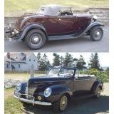
This may help. Pages taken from John Connelly's sales brochure of a few years ago.
http://www.columbiatwospeedparts.com/ |
|
|
|
| Sponsored Links (Register now to hide all advertisements) |
|
|
|
02-24-2018, 04:42 PM
|
#3 |
|
Senior Member
Join Date: May 2010
Location: Green Bay
Posts: 391
|
Glen: Thanks for the reference. In the second picture the bottom bracket is what I would like to see install on a 35 clutch pedal. Trying to fit it to a 39 pedal assembly. Dave/Green Bay
|
|
|
|
|
02-25-2018, 09:13 AM
|
#4 |
|
Senior Member
Join Date: Sep 2014
Location: Wiscasset, Maine
Posts: 1,981
|
Sponsored Links (Register now to hide all advertisements)
From what I could find, the bracket slips over the clutch release arm and not over the clutch pedal arm. I have a 40 Columbia in my 32 and the 40 does slip over the clutch pedal arm. From the 35-36 instructions: OPERATION No. 8 (USE SUB-ASSEMBLY No. 5 ) Install clutch pedal valve on bell housing See illustration No. 8. Remove center cap screw on left side of bell housing and attach valve at this point using longer cap screw provided with valve. IMPORTANT: Dowel on bracket of valve must fit dowel hole in bell housing which locates valve in correct position. Disconnect clutch pedal spring from clevis pin. Remove clutch pedal clevis pin. Assemble pressed steel lever extension over clutch pedal as shown in illustration No. 8 and letter "J" on General Diagram. This lever extension must be a snug fit over clutch shaft so that there is no lost motion. Insert new clevis pin furnished. Replace clutch pedal spring. Assemble pedal valve link, as shown in illustration No. 8. |
|
|
|
|
«
Previous Thread
|
Next Thread
»
 Linear Mode

|
|

| Sponsored Links (Register now to hide all advertisements) |
|
|
All times are GMT -5. The time now is 03:32 AM.