|
|||||||


| Sponsored Links (Register now to hide all advertisements) |
|
|
 |

|
Thread Tools | Display Modes |
 06-25-2020, 11:52 AM
|
#1 |
|
Senior Member

Join Date: May 2010
Location: Long Island, NY
Posts: 3,463
|
I need some help to Ford historians to determine how the factory balanced the engine's rotating assembly during Model "A" production. What I guess is:
>Pistons & connecting rods were individually weighed and sorted into sets by weight; > After assembling with wrist pins & rings, the assemblies were weighed and sorted into sets by weight; > The crankshaft was spin balanced by itself on a table atop springs. No weights were added to the crankshaft throws to account for piston assemblies, friction, etc. Holes were drilled into the crankshaft until the table's motion met a prescribed amount; > The flywheel was statically and dynamically balanced without the clutch. > The clutch was balanced by its supplier. Is this the way Ford did it?
__________________
Bob Bidonde |

|

|
|
06-26-2020, 08:18 AM
|
#2 |
|
Senior Member

Join Date: May 2010
Location: Eastern Tennessee
Posts: 11,508
|
Bob, this is something that will likely take some time to research to come up with an answer. More time than I have right now unfortunately. As far as pistons & rods, I recall on the prints it stated that the units of weights was in grams. Because of the small differential in weights that were acceptable, I doubt they were sorted & matched.
Something I also recall on my crankshaft print is the cranks were spec-ed to be in balance in ounce inches, -which an ounce inch is about ¾ of a gram. Today we tend to overbalance on rebuilds without using bobweights which does compensate for rod & piston weights however I know that Ford used outside suppliers for wrist pins and pistons, and it specified what the weight tolerance was to be. I'd say since all of these weights were within a tight spec, they did not worry with spec matching. Also, my guess is once the crankshaft was ground, it was balanced in that department to the spec weight, and each component was done similarly in different locations. Therefore I doubt there will be any information in Engineering Information sheets or in Foreman's Logs as to protocol or procedures. |
|
|
|
 )
)| Sponsored Links (Register now to hide all advertisements) |
|
|
|
06-26-2020, 10:52 AM
|
#3 |
|
Senior Member
Join Date: Jun 2015
Posts: 1,414
|
See if you can get ahold of the 1932 Ford V8 vhs tape produced by Silverado Productions (Loren Sorenson) or perhaps Utube. It has soundtrack and shows the factory processes for engine parts, drilling the flywheel, much as you state, etc. which carried over from the Model A..
|
|
|
|
|
06-26-2020, 12:34 PM
|
#4 |
|
Senior Member
Join Date: May 2010
Location: Long Island, NY
Posts: 3,463
|
Brent, Duke,
Thanks for the info.
__________________
Bob Bidonde |
|
|
|
|
06-26-2020, 08:18 PM
|
#5 |
|
Senior Member

Join Date: Dec 2014
Location: Germantown,TN
Posts: 516
|
Page 25 May-June Model A News shows a picture taken in the Ford engine assembly area of the piston and connecting rod assemble’s being matched on a balance.
|
|
|
|
|
06-28-2020, 11:39 AM
|
#6 |
|
Senior Member
Join Date: Jun 2010
Location: Temecula, CA
Posts: 4,084
|
Sponsored Links (Register now to hide all advertisements)
|
|
|
|
|
06-28-2020, 01:04 PM
|
#7 |
|
Senior Member
Join Date: Aug 2010
Location: SF Bay Area
Posts: 193
|
Nor is it required on a 4 cyl engine to use bob weights on the crankshaft when dynamically balancing it.
|
|
|
|
|
06-28-2020, 04:15 PM
|
#8 |
|
Senior Member

Join Date: May 2010
Location: Potomac, Maryland
Posts: 911
|
....adding to what Brent said, each of those operations underwent a weight equalization process. Here for example it the description of how the pistons were machined to the exact weight (in grams as Brent noted):
Brad in Maryland |
|
|
|
|
06-28-2020, 04:39 PM
|
#9 |
|
Senior Member
Join Date: May 2010
Location: Potomac, Maryland
Posts: 911
|
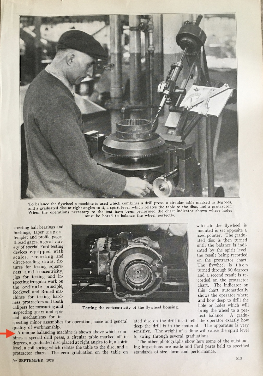
....and here is a description of how the flywheels were balanced (description starts at the bottom of the page to the left by the red arrow; also note the caption under the photo):
 Brad in Maryland Last edited by Brad in Germany; 06-28-2020 at 05:57 PM. |
|
|
|
|
06-29-2020, 09:18 AM
|
#10 |
|
Senior Member
Join Date: May 2010
Location: Long Island, NY
Posts: 3,463
|
Brad, thank you for sharing the balancing text. So what I have learned so far is during Model "A" production, the individual parts of the engine's rotating assembly were balanced, and not balanced as a set. However, the crankshaft was statically and dynamically balanced by itself without account for the weights of the piston assemblies.
__________________
Bob Bidonde |
|
|
|
|
06-29-2020, 01:02 PM
|
#11 |
|
Senior Member
Join Date: May 2010
Location: Potomac, Maryland
Posts: 911
|
Bob: Yes, that is correct. As for the Model A crank shaft, there were 77 operational steps in the production and machining of each crank shaft. The balancing of the crank shaft was done in a sup-operation of step 77 (the last operational step).
Here is the list of the final steps of the crank shaft production where you can see step 77 consists of checking the balance of the crank using a Gisholt Precision balancing machine and then step 77A drilling out excess material to bring the crank into balance: ....and a photo of that drilling operation to balance the crank shaft (see figure 3, top right, in this photo): 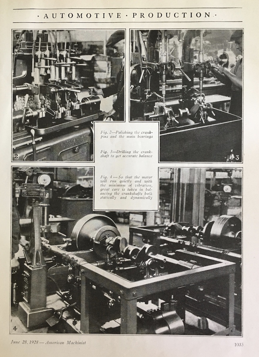 Note also the comment for figure 4 in the above photo.....about statically and dynamically balancing the crank. Brad in Maryland |
|
|
|
|
06-29-2020, 06:44 PM
|
#12 |
|
Senior Member

Join Date: Jun 2010
Location: San Antonio, Texas
Posts: 16,420
|
There were some strange methods to dynamically balance things before accelerometer devices or velocity sensors were developed. I'm not sure what would have been used in the 1928/31 time frame. The V8 engines crankshaft was done differently and by that time Ford likely had state of the art equipment. The films they made show some of that equipment but I haven't seen any in the Model A time frame yet. Crankshafts are a soft bearing shaft that requires a bit more set up than hard bearing shafts.
Static balancing would have been with very rudimentary devices but they are good for a quick reference check. This link has some info on the Gisholt machines. The shaft was rotated on a frame that was on pivots and attached to the vibration meter which was based on inch ounces. This method is old hat since it physically measured the amount of movement but a good operator could balance the shafts well enough. A modern machine would do it with more immediate accuracy but both will do the job with an experienced operator. https://babel.hathitrust.org/cgi/pt?...iew=1up&seq=24 Last edited by rotorwrench; 06-29-2020 at 07:19 PM. |
|
|
|
|
06-30-2020, 09:25 AM
|
#13 |
|
Senior Member
Join Date: May 2010
Location: Long Island, NY
Posts: 3,463
|
Having studied all of the materials posted above, and having done some research of factory films on YouTube, I conclude that the factory balanced the rotating assembly of the Model A's engine as follows:
>Pistons were cast heavy so there was material for removal during balancing; >After the pin hole and exterior dimensions were finish machined, pistons were put into a special machine where they were weighed and the weight to be removed to reach 1 pound, 1.875 ounces within a few grams was determined. The weight was removed from the inside diameter of the skirt, and when the chips machined off equaled the weight to be removed, the piston was balanced; >After assembly of a piston, pin, rings, & rod with shims & castle nuts, the assemblies were compared on a beam balance scale. Assemblies were grouped into sets of 4 by weight. By the way, the rod babbitt would have final sized beforehand; >The crankshaft was statically balanced on parallel rails. Material was drilled-away until the crankshaft remained still at any rotation. Static balancing was a prerequisite to spin balancing; >Following static balancing, the crankshaft was spin-balanced on a table where the table was totally supported on springs. The crankshaft was spun to about 500 RPM and the movement of the table was measured. Material was drilled out of the crankshaft until the table motion reached a predetermined amount; >The flywheel was balanced separately and only statically using a bubble type machine. Material was removed by drilling holes in the outer rim. I was puzzled by the specification of "ounce-inches" for the crankshaft balance. What this means is that a certain amount of unbalance weight located a certain distance from the crankshaft's axis of rotation was the acceptance criteria for balancing. For a hypothetical example, the table's motion could be calibrated to an amount produced by 0.2 of an ounce situated 1" from the axis of rotation.
__________________
Bob Bidonde Last edited by Bob Bidonde; 06-30-2020 at 09:33 AM. |
|
|
|
|
06-30-2020, 12:53 PM
|
#14 |
|
Senior Member
Join Date: Jun 2010
Location: San Antonio, Texas
Posts: 16,420
|
Now days we generally use a measure of velocity for balance reading. IPS or inches per second is a common imbalance reference. The accelerometers use piezoelectric crystals to measure the amount of movement. These velocity sensors give a much more sensitive movement reading. We usually try to balance rotors to 0.1 IPS but most will work OK at 0.2 IPS. Sometimes it's not possible to get then less than that depending on the configuration of the shaft or rotor being balanced. A strobe light is used to find the angle of the shift off center of the shaft. Some computerized type machines don't use a strobe if they are properly programmed for the shaft or rotor being balanced. This is what tells a person where to remove or add weight.
|
|
|
|
|
06-30-2020, 10:14 PM
|
#15 |
|
Senior Member

Join Date: Nov 2018
Location: Farmington MI
Posts: 284
|
While we are on the subject balancing stuff; you may be interested in seeing the machines that are used these days. Micro Poise (MP) Balance Engineering Co. Troy MI.
Back when I worked for GM , Cadillac in the 60's and 70's we used propriety balancing machines manufactured by General Motors, There was a small division "GM Balance Engineering". I believe that there is a historic connection to MP Balance Engineering. https://www.machinetools.com/en/comp...neering/models Joe B Last edited by JoeCB; 06-30-2020 at 10:24 PM. |
|
|
|
|
07-01-2020, 11:40 AM
|
#16 |
|
Senior Member
Join Date: Jun 2010
Location: Temecula, CA
Posts: 4,084
|
All very interesting! Thanks Brad and Joe!
|
|
|
|
|
07-02-2020, 08:08 AM
|
#17 |
|
Senior Member
Join Date: May 2010
Location: Long Island, NY
Posts: 3,463
|
I am in the process of building a Power Point presentation for my local Model "A" club that highlights the causes of engine vibrations, and the steps taken to make vibration feel better. In the presentation, I am comparing how the factory balanced the Model "A's" engine to modern methods a rebuilding shop might use.
The info posted above gave me direction for further investigation and learning about unbalances and balancing. Thanks again all for your help.
__________________
Bob Bidonde |
|
|
|
|
07-02-2020, 11:53 PM
|
#18 |
|
Senior Member
Join Date: May 2010
Location: Potomac, Maryland
Posts: 911
|
Bob:
Here is a similar article that appeared in the 1 April 1928 issue of Ford News describing the balancing process of the flywheel: 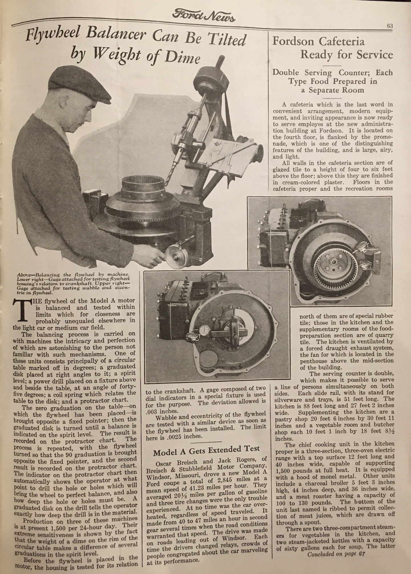 ....and one on balancing the crank from the 1 May 1928 issue of Ford News: 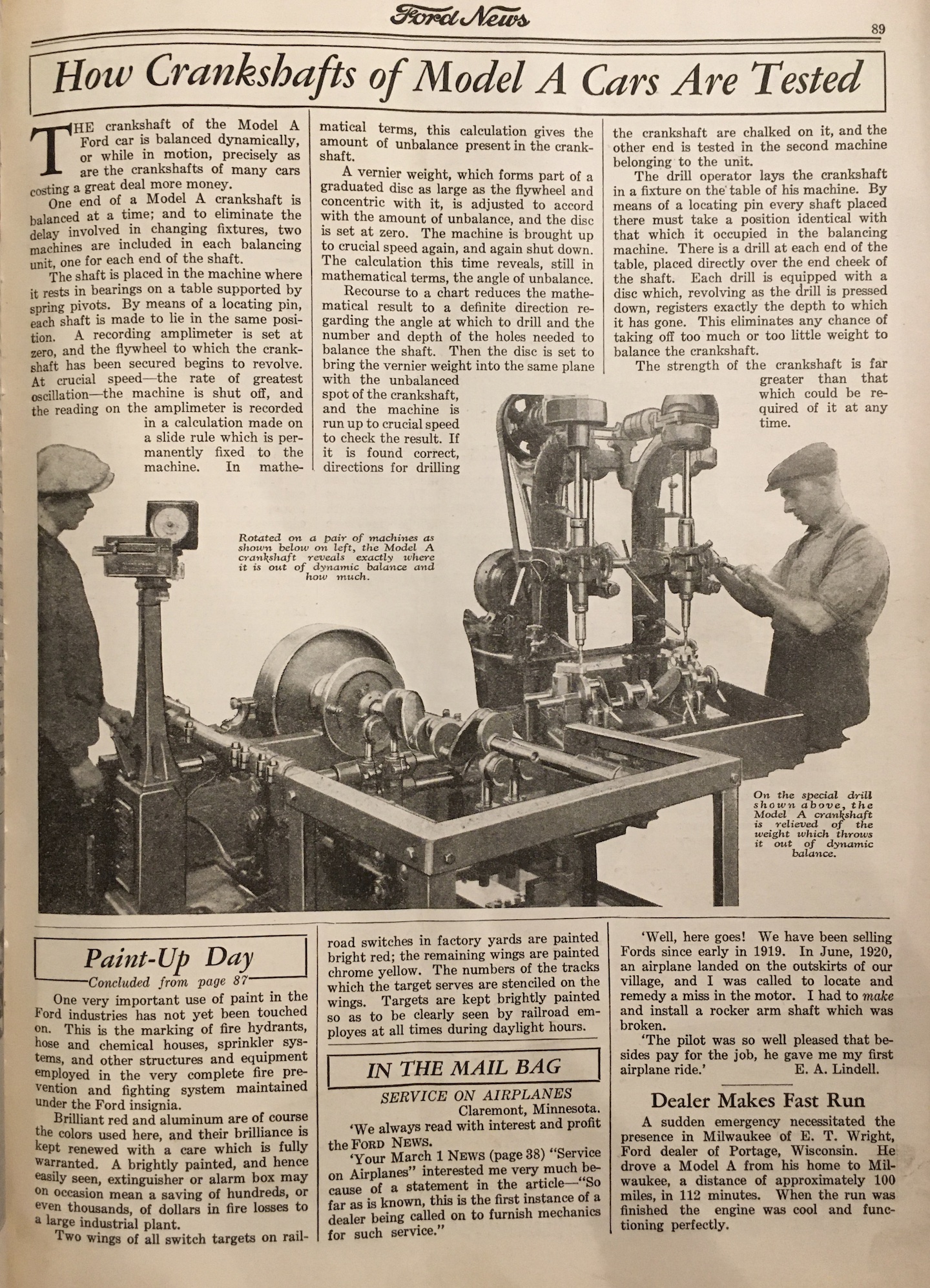 ....and the blurb, extracted from the 1929 Ford Model A dealer album, talking about balancing the engine components: 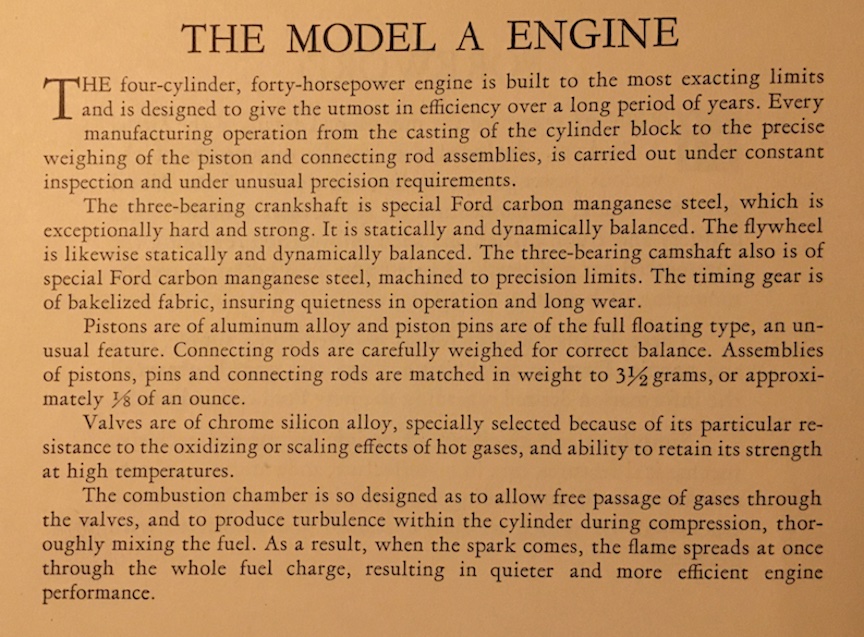 Brad in Maryland |
|
|
|
|
07-03-2020, 08:53 AM
|
#19 |
|
Senior Member
Join Date: Jun 2010
Location: San Antonio, Texas
Posts: 16,420
|
This is off topic a bit but I wanted to add it in since it relates to crankshafts & flywheels. Some of the helicopters I work on have a crankshaft driven fan that is either directly attached to the drive end of the crankshaft or attached through an extension shaft and bearing assembly. The one that is directly attached is generally only balanced when an imbalance is suspected or after a related part is replaced. The ones with the extension have to be checked any time they are removed and reinstalled for maintenance due in large part to the use of a tapered shaft.
I use the same balance machine that is used for rotor balance in the T/R configuration. The accelerometer or vibration sensor is mounted vertically pointing up on engine nose case for directly attached flywheel fans or on the extension shaft bearing housing for those types pointing down. The accelerometer will work the same either way since it receives vibration in a 360 degree plane. The balance machine is just a small electronic box with an IPS meter and several function switches & buttons that is all powered by a 12 or 24 volt battery. I won't get into it's function other than the fact that this particular model does use a strobe light to get the angle of imbalance movement around the crankshaft's circumference. Before the ground run, a piece of reflective tape is installed at any point on the flywheel or fan to use as a reference for where the imbalance is. The machine is set to the full speed rpm of the applicable engine in the test. The engine ground run is started and it's eventually run up to operating rpm. The strobe light is used to see what clock angle the reflective tape is at while the balance machine is further tuned to the actual RPM. The IPS meter reading is recorded and the test is complete with the normal shut down procedure. After shut down, the crankshaft is rotated till the location of the reflective target tape is in the same clock angle location that was observed during the test run. Designated by where the accelerometer is mounted in relation to the clock angle of the shaft, the place where the weight will be added is either 12 o'clock or 1 o'clock depending on the application. The manufacturer of the aircraft has a chart that is read using the IPS reading and it will instruct how much weight is to be added to correct the imbalance condition. When the weight installation is complete. The engine ground run vibration check is performed again to see if the imbalance was eliminated or not. If it is not at least 0.2 IPS or less, the weight will be adjusted again until it is within acceptable limits with a further balance run check. This process is done on propellers of airplanes as well as rotors and engines of helicopters. Turbine engines are checked but obviously no adjustments can be made externally but it will let the maintainers know the condition of the turbine hot section and compressor rotors. When I was working in turbine overhaul some years ago, I worked with a Balreco balance machine to balance the turbine and compressor rotors before the engines were reassembled. It also used a strobe light and an IPS meter to find the imbalance location, I used soft wax added to the light side to balance each end of the rotor so that I would have a reference as to how much weight had to be removed from a point that was 180 degrees from the light side (heavy side). There was a protruding ring on the rotors where metal could ground off to correct the imbalance. A person has to be real careful while grinding on $5k rotor wheel. The wheels are likely a lot higher in price now days. Last edited by rotorwrench; 07-03-2020 at 09:09 AM. |
|
|
|
|
«
Previous Thread
|
Next Thread
»
| Thread Tools | |
| Display Modes | |


 Linear Mode

|
|

| Sponsored Links (Register now to hide all advertisements) |
|
|
All times are GMT -5. The time now is 10:17 AM.