|
|||||||


| Sponsored Links (Register now to hide all advertisements) |
|
|
 |

|
Thread Tools | Display Modes |
 01-20-2020, 08:54 PM
|
#1 |
|
Senior Member
Join Date: Aug 2018
Location: Ottawa, ON
Posts: 850
|
I'm looking for a drawing of the exhaust port layout so I can fab up a plate for my engine stand. I've searched but I couldn't find anything on the net. If you have one, or if you could point me in the right direction, it would be much appreciated.
|

|

|
|
01-20-2020, 08:56 PM
|
#2 |
|
Member Emeritus
Join Date: Nov 2012
Location: Wichita KS
Posts: 16,132
|
I would think an exhaust gasket as a pattern would be the way to go, that is what I did when I fabricated one. (brain short circuit, this will not work with a flathead, individual gaskets!). Another way to go about it is use some light card stock type of material and do an impression directly off the block. You just need the outside four bolt holes. Some examples (not mine).
Last edited by JSeery; 01-21-2020 at 08:36 AM. |
|
|
|
| Sponsored Links (Register now to hide all advertisements) |
|
|
|
01-20-2020, 09:47 PM
|
#3 |
|
Senior Member

Join Date: Dec 2013
Location: Minnesota, Florida Keys
Posts: 10,303
|
Who makes flathead exhaust gaskets that are one piece per side? I have only seen the individual port kind.
|

|
|
|
01-20-2020, 10:25 PM
|
#4 |
|
Senior Member

Join Date: May 2010
Location: MN
Posts: 7,053
|
Take some grease and put a slight amount around the area (or spray WD40). Press the gasket/template material up to it. Boom... template.
Works the same with some paper taped to the spot and a dirty finger rubbing over the area. Like a art "rubbing'. https://en.wikipedia.org/wiki/Rubbing ***You're probably looking for a waterjet ready eps/dwg/vector. Not sure on a link, I could make one, no block not used for me*** . Last edited by Tinker; 01-21-2020 at 12:09 AM. |
|
|
|
|
01-20-2020, 10:39 PM
|
#5 |
|
Senior Member

Join Date: Nov 2015
Location: North Pole, Alaska
Posts: 2,651
|
I just used an exhaust manifold for the pattern. Of course you must reverse it, unless you’re using it on the other side

|
|
|
|
|
01-20-2020, 11:27 PM
|
#6 |
|
Senior Member
Join Date: Jan 2011
Location: sw minnesota
Posts: 4,567
|
Sponsored Links (Register now to hide all advertisements)
|
|
|
|
|
01-21-2020, 03:38 AM
|
#7 |
|
Senior Member
Join Date: Aug 2018
Location: Ottawa, ON
Posts: 850
|
Thanks for the suggestions. The problem I have is that I don't have a manifold, and the gaskets I have are the individual ones for each port. I have the engine, but it is all wrapped in plastic which I don't really want to remove just yet as I still need to clean up my workshop which is a total mess.
|
|
|
|
|
01-21-2020, 08:28 AM
|
#8 |
|
Member Emeritus
Join Date: Nov 2012
Location: Wichita KS
Posts: 16,132
|
To answer your original question, I don't know of any pattern that is available. It is too easy to make one. Might get someone with a head or block to make you one.
You could go ahead and get the manifolds you intend to use? Last edited by JSeery; 01-21-2020 at 08:34 AM. |
|
|
|
|
01-21-2020, 08:30 AM
|
#9 | |
|
Member Emeritus
Join Date: Nov 2012
Location: Wichita KS
Posts: 16,132
|
Quote:
|
|
|
|
|

|
01-21-2020, 08:51 AM
|
#10 |
|
Senior Member
Join Date: Aug 2018
Location: Ottawa, ON
Posts: 850
|
My machinist had a block. I’ll see if i can arrange to have access so I can trace out a pattern.
|
|
|
|
|
01-21-2020, 08:54 AM
|
#11 |
|
Member Emeritus
Join Date: Nov 2012
Location: Wichita KS
Posts: 16,132
|
It is fairly easy and quick to hold some poster board type of paper up to the block and just use your finger to press around the bolt holes. Just make sure the paper stays put and doesn't move.
|
|
|
|
|
01-21-2020, 09:15 AM
|
#12 |
|
Senior Member
Join Date: Nov 2015
Location: North Pole, Alaska
Posts: 2,651
|
Or, screw four studs in the outer ports and lay the poster board on them, slight tap with a hammer and viola!
|
|
|
|
|
01-21-2020, 09:24 AM
|
#13 |
|
Senior Member

Join Date: May 2010
Location: Solihull, England.
Posts: 8,744
|
Make all the holes bigger than 7/16" so the adaptor can fit both sides. 1/2" is ok.
|
|
|
|
|
01-21-2020, 09:52 AM
|
#14 |
|
Senior Member

Join Date: Jul 2010
Location: 36 miles north of Albany NY
Posts: 2,943
|
Got mine from Stumpy
https://www.stumpysfabworks.com/stor..._Products.html Scroll down to flathead. It's 4 below zero and I have a flathead mounted on mine in a portable garage, otherwise I'd make a cardboard tracing of mine and sent it to you. Maybe if your still looking I do it in the spring. Pm me if your interested. |
|
|
|
|
01-21-2020, 10:33 AM
|
#15 |
|
Senior Member
Join Date: May 2010
Posts: 886
|
I take some grade 5 bolts cut the thread part off , grind the flat cut off end to a point , screw the bolt ends in the block put some tool makers ink, magic marker ,momma's cake coloring etc. on the ground pointed ends protruding from the block, grabbed a 1x4 and a mallet tapped the board against the pointed studs then drill the 1x4 as a template and transfer punch a 1/2'' plate for the block mounting flange , I take a 2'' piece of cold rolled cut to 45 degrees weld to the 1/2'' plate to fit my engine stand head. I keep a selection of different pointed bolts used to transfer bolt patterns ,I also set some threaded cut off bolts up in a lathe then drill through the center and use as a starting guide for center drilling bolts that are broken off below the surface such as head bolts.
Last edited by Fordestes; 01-21-2020 at 11:01 AM. |
|
|
|
|
01-21-2020, 11:40 AM
|
#16 |
|
Senior Member
Join Date: May 2010
Location: NJ
Posts: 6,177
|
What's your mailing address?
I'll just trace my angle adapter and mail it to you. |
|
|
|
|
01-21-2020, 03:20 PM
|
#17 |
|
Senior Member

Join Date: Jul 2019
Location: Southern Oregon
Posts: 782
|
This is the Ford drawing. A little hard to read with this upload but, the center distance is 7.812 or 15.624, end to end. 1.437 or 2.874 on the flange holes, set at 30 deg.
__________________
Frank '35 Ford Model 51 '48 Ford F3 '54 Ford Tudor Mainline |
|
|
|
|
01-21-2020, 03:44 PM
|
#18 |
|
Senior Member

Join Date: Jun 2010
Location: Atlanta GA
Posts: 505
|
You want a tracing off of my Stumpy mount, or a header? I could do that for you.
|
|
|
|
|
01-21-2020, 04:22 PM
|
#19 | |
|
Member Emeritus
Join Date: Nov 2012
Location: Wichita KS
Posts: 16,132
|
Quote:
|
|
|
|
|
|
01-21-2020, 04:39 PM
|
#20 |
|
Senior Member
Join Date: Aug 2018
Location: Ottawa, ON
Posts: 850
|
Excellent. Thanks guys. Between the drawing and my gaskets, I should figure it out. Trust me, if I lived in the USA, I would have just purchased one, but with the exchange rate, taxes, and brokerage fees, it gets spendy fast. I'll post up pics when I'm done, hopefully in the next week.
|
|
|
|
|
01-21-2020, 05:26 PM
|
#21 |
|
Senior Member
Join Date: Dec 2013
Location: Minnesota, Florida Keys
Posts: 10,303
|
WOW. 14 posts do do something this simple?
|
|
|
|
|
01-21-2020, 06:18 PM
|
#22 |
|
Senior Member
Join Date: Jan 2011
Location: sw minnesota
Posts: 4,567
|
15, i thought they are 45* ?
|
|
|
|
| Sponsored Links (Register now to hide all advertisements) |
|
|
|
01-23-2020, 05:38 PM
|
#23 |
|
Senior Member
Join Date: Aug 2018
Location: Ottawa, ON
Posts: 850
|
16. Made a template off the block at the machinist's shop. You know engineers have to complicate everything. 😏
|
|
|
|
|
01-23-2020, 06:46 PM
|
#24 |
|
Senior Member
Join Date: May 2010
Location: Solihull, England.
Posts: 8,744
|
You only need the outer holes so they will do for both sides.
|
|
|
|
|
01-23-2020, 07:05 PM
|
#25 |
|
Senior Member
Join Date: Aug 2018
Location: Ottawa, ON
Posts: 850
|
Got it. We checked the other side of the block and the outer holes lined up as you said, but I can almost guarantee that I would have drilled out the middle holes, so thanks for reminding me.
|
|
|
|
|
01-23-2020, 08:06 PM
|
#26 |
|
Senior Member

Join Date: May 2010
Location: So Minn
Posts: 1,565
|
Sponsored Links (Register now to hide all advertisements)
|
|
|
|
|
01-23-2020, 08:42 PM
|
#27 |
|
Senior Member
Join Date: Aug 2018
Location: Ottawa, ON
Posts: 850
|
Yep. After playing around with some printer paper and a pencil, that is exactly what the machinist did, instead just with a heavier piece of cardboard and no hole punch.
|
|
|
|
|
01-23-2020, 08:47 PM
|
#28 |
|
Senior Member
Join Date: May 2010
Location: So Minn
Posts: 1,565
|
Cool. I like to use the aluminum sheet because the holes "don't move" if you have to use it again.
|
|
|
|
|
01-23-2020, 11:18 PM
|
#29 |
|
Senior Member

Join Date: Oct 2011
Location: Shelton, WA
Posts: 3,799
|
If it were me, I'd clamp an exhaust manifold on the piece of steel I was going to use and using transfer punches mark the holes and them take them to the drill press. Why go to all the trouble of making a template, then transferring those marks to your steel? You have a couple of chances of having something move and be off.
Or if you really wanted to make it complex, create a DXF file and take that to a CNC mill or a laser cutter! |
|
|
|
|
01-23-2020, 11:47 PM
|
#30 |
|
Member Emeritus
Join Date: Nov 2012
Location: Wichita KS
Posts: 16,132
|
He does not have a manifold, that's what started all of this.
|
|
|
|
|
02-03-2020, 08:33 PM
|
#31 |
|
Senior Member
Join Date: Aug 2018
Location: Ottawa, ON
Posts: 850
|
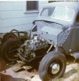
Finished off the adapter. Fits great. I just had to trim the corner like in the previous pics, and cut down my 1.25" lg bolts to 3/4". Yes, I lifted with only two manifold bolts and a chain. Lol.
|
|
|
|
|
02-03-2020, 08:58 PM
|
#32 |
|
Member Emeritus
Join Date: Nov 2012
Location: Wichita KS
Posts: 16,132
|
Looks great!
|
|
|
|
|
02-04-2020, 04:00 AM
|
#33 |
|
Senior Member
Join Date: May 2010
Location: Solihull, England.
Posts: 8,744
|
Only two manifold bolts?
A bit lavish ain't ya? One would have done. 
|
|
|
|
|
02-04-2020, 04:47 AM
|
#34 |
|
Senior Member
Join Date: Aug 2018
Location: Ottawa, ON
Posts: 850
|
LOL. True, but that's what the machinist used. He suggested I make a plate to cover the intake with a couple lifting points which I'll do soon. First, I want to get a dial gage and fixture so I can mark TDC on my pulley, which I may need to purchase as mine is some cobbeled up affair with a third groove crudely welded on.
|
|
|
|
|
02-04-2020, 11:27 AM
|
#35 |
|
Senior Member
Join Date: Jan 2011
Location: sw minnesota
Posts: 4,567
|
this one is a bit elaborate, but i hope to use it until my toes point up. cut out to match an intake gasket, so good for painting, lifting, or storing a flathead
|
|
|
|
|
02-04-2020, 02:30 PM
|
#36 |
|
Senior Member
Join Date: Aug 2018
Location: Ottawa, ON
Posts: 850
|
Wow. That is brilliant. I like the idea that you matched the intake profile. I'm leaning towards painting my block a different colour than that of the heads and intake, so that would be perfect for such a scenario. The adjustable lift is just icing on the cake. Someone should be selling this concept.
|
|
|
|
|
02-04-2020, 02:58 PM
|
#37 |
|
Senior Member

Join Date: Dec 2010
Location: East Coast in CT
Posts: 1,524
|
Unable to remove my post sorry.
__________________
I use the F word a lot no not that word these words Flathead , Focus and Finish. "Life Member of the Bonneville 200 MPH Club using a Ford Flathead block" Owner , Builder, Driver of the First Ford Flathead bodied roadster to run 200 MPH Record July 13, 2018 LTA timing association 200.921 in one and a half miles burning gasoline. First ever gas burning Ford flathead powered roadster to run 200 MPH at Bonneville Salt Flats setting the record August 7th 2021 at 205.744 MPH |
|
|
|
|
«
Previous Thread
|
Next Thread
»
 Linear Mode

|
|

| Sponsored Links (Register now to hide all advertisements) |
|
|
All times are GMT -5. The time now is 06:13 AM.