|
|||||||


| Sponsored Links (Register now to hide all advertisements) |
|
|
 |

|
Thread Tools | Display Modes |
 01-26-2012, 03:50 PM
|
#1 |
|
Senior Member

Join Date: May 2010
Location: Jordan, MN
Posts: 1,411
|
I was ordering parts and noticed...
a "NEW" item listed on Snyders website. PRESS RELEASE After two years of engineering, tooling and actual road testing, Performance Engineering proudly announces that their NEW, FULLY UPGRADED CONNECTING RODS WITH REPLACEABLE BEARINGS are now available for both Model A and Model T applications. The combination of modern, high quality materials and technological improvements allow these components to be suitable for Stock, Performance and Racing applications. Snyder's is making and selling new insert bearing connecting rods. The insert bearing shells have the side thrust surfaces as part of the insert component. I ordered a set to study and use. The sizing of the insert bearings are available in standard through .040 undersize. I will follow up with comments when they arrive early next week.   Snyder's Insert Snyder's InsertInteresting...note the two relief channels in the side thrust surface to allow oil to flow to and wet the area. I spoke to Snyder's this morning regarding the fit of the piston pin. They stated: Rods have the wrist pin bushing pressed in, oil holes drilled, and rough bored. You MUST hone the wrist pin bushings to match the wrist pins in your pistons. Shoot...I was hoping they would pre-fit them to the pistons they sell. Cost is $75.00 each with a set of insert bearings at $110.00 on their website. Cost of set of 4 with insert bearings $410.00, no exchange, compared to the cost of their babbitt rods set at $236 plus the cost of shipping your old rods to them for exchange...about $14.00. So $250 for babbitt vs. $410.00. I will put these rods in a test engine this month and report on the results. It's good to have options! Good Day! Dave in MN www.durableperformance.net Last edited by Dave in MN; 01-26-2012 at 04:49 PM. |

|

|
|
01-26-2012, 04:01 PM
|
#2 | |
|
Senior Member

Join Date: May 2010
Location: NC
Posts: 2,975
|
Quote:
except they are for the Chev 283 pistons. They look really good. I have not check them yet, and have not looked at the rod bearings yet. But I though they were like rod bearings for other cars with out the thrust. I will check later. |
|
|
|
|

| Sponsored Links (Register now to hide all advertisements) |
|
|
|
01-26-2012, 04:06 PM
|
#3 |
|
Senior Member

Join Date: May 2010
Location: South California
Posts: 6,188
|
Dave , thanks for that! I'll definitely follow your info.
Inserts: $410 + $14 = $424. |
|
|
|
|
01-26-2012, 04:20 PM
|
#4 | |
|
Senior Member
Join Date: May 2010
Location: Jordan, MN
Posts: 1,411
|
Quote:
From what you describe you have a set of the rods made by AER (Antique Engine Rebuilding), Skokie. Snyder's new connecting rod offering do not fit the 283 pistins. When purchased through Snyders the AER rods cost $580.00 for a set of 4 with inserts included for the Model A piston and $570.00 a set for the 283 piston. The Snyder rod set with inserts is about $170.00 less than the cost of the AER rod set. Time will tell who makes the better rod! 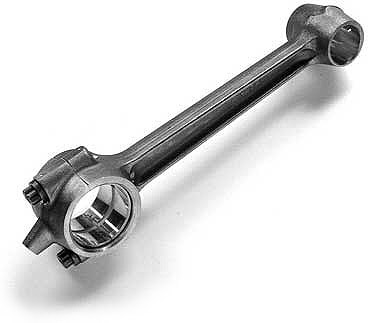 AER Rod and Insert for the Model A Piston (Antique Engine Rebuilding, Skokie IL) Dave in MN Last edited by Dave in MN; 01-26-2012 at 04:35 PM. |
|
|
|
|
|
01-26-2012, 04:21 PM
|
#5 |
|
Member
Join Date: May 2010
Location: New Haven, IN
Posts: 86
|
I believe these are the same as those by Rich @ Antique Engine rebuilders in Skokie. I have his insert rods and they're great!
|
|
|
|
|
01-26-2012, 04:38 PM
|
#6 | |
|
Senior Member
Join Date: May 2010
Location: Jordan, MN
Posts: 1,411
|
Sponsored Links (Register now to hide all advertisements)
Quote:
No they actually are not...look closely. I have added photos of the rods the two suppliers make in my earlier posts. Note the inserts from Snyder have the side thrust surfaces as part of the bearing. AER rods, from Skokie, use the actual rod as the thrust surface. I agree with you about the quality of AER's rods. I have about 60 engines out with the AER rods and they have been great. Dave in MN www.durableperformance.net |
|
|
|
|
|
01-26-2012, 05:55 PM
|
#7 |
|
Senior Member

Join Date: Jul 2010
Location: Oslo, Norway
Posts: 521
|
Why is the oil groove in the insert going around the insert instead of being made in the axis of the crancshaft or at an angle.
One of my engines had rod bearings with oil grooves like these (not inserts though) The oil grooves had (not) worn the crankshaft leaving a raised ring around the journals .............. |
|
|
|
|
01-26-2012, 05:57 PM
|
#8 |
|
Senior Member
Join Date: May 2010
Location: Windy City
Posts: 2,919
|
I'll take a pass and stick with AER rods for several reasons:
1. This is a step BACKWARDS in design. Modern engines do not use bearing material as a side thrust on rod inserts. Unless you have a bent rod, there is no side thrust. If such a rod bearing flange were beneficial you would find then on every modern high perf engine. None. 2. STD size is different on a Burlington crank than a stock A crank. The Burlington is 0.001 smaller. AER has special -0.001 inserts for that app. Using the STD Snyder inserts with that crank would give you an unacceptable 0.0025 clearance to start. 3. There is no mention of what the bearing construction is- is there a base steel shell with copper first then laminated Babbitt or is it a solid? How thick is the Babbitt layer? More is NOT better. 4. They only fit "A" style pistons. I'm sold on lighter weight 283 style pistons with modern rings. This requires a slightly longer rod with a different pin hole, available from AER. 5. I don't want to be the guinea pig. |
|
|
|
|
01-26-2012, 08:46 PM
|
#9 |
|
Senior Member

Join Date: May 2010
Location: Eastern Tennessee
Posts: 11,508
|
Mike, I am not so sure the Chevy pistons are lighter than Snyder's pistons. I think it is just that they are cheaper than Snyders, ...and there is a little less drag with the thinner rings. Probably for what you gain in piston dwell (longer rod) you give up in the Chev piston having the eyebrow reliefs in the face.
|
|
|
|
 )
)|
01-26-2012, 09:04 PM
|
#10 | |
|
Senior Member
Join Date: May 2010
Location: NC
Posts: 2,975
|
Quote:
|
|
|
|
|
|
01-26-2012, 09:04 PM
|
#11 |
|
Senior Member

Join Date: May 2010
Location: Southern Upstate New York
Posts: 1,160
|
How about Pete's 283 style pistons? They fit standard length Model A rods, use modern thin rings and don't have the eyebrow on the face.
__________________
AL in NY |
|
|
|
|
01-26-2012, 09:21 PM
|
#12 | |
|
Senior Member
Join Date: May 2010
Location: NC
Posts: 2,975
|
Quote:
|
|
|
|
|
|
01-26-2012, 09:29 PM
|
#13 |
|
Senior Member
Join Date: May 2010
Location: Windy City
Posts: 2,919
|
From my build records last year, before weight match balancing... WITH FITTED PINS:
Egge 1104 (A style full skirt, modern narrow rings), +0.060: 747g, 745g, 748g, 746g (Hypereutectic 390 alloy, superior machine finish and cam shaped skirt!!!) Silvolite #1412 +0.060 (std. 283 chev) 783g, 781g, 784g, 783g (Std Al/Si alloy) THE LIGHTWEIGHT WINNER: KB Performance #165 +0.060 (283 racing piston) 503g, 504g, 501g, 503g (Hypereutectic 390 alloy, this set also had lightweight 108g pins) ...I do not have any std A +0.060 pistons to weigh or build weight records... Some errata for those interested: Piston compression height: Stock A- 1.875, 283 Chev- 1.805 Rod length: Stock A- 7.500, Special AER rods for 283 pistons- 7.570 Weight of AER/283 rods: 707g plus 52g for bearing shells. I wonder what the Snyder rods and inserts weigh? |
|
|
|
|
01-26-2012, 09:33 PM
|
#14 | |
|
Senior Member

Join Date: May 2010
Posts: 3,099
|
Quote:
 
__________________
http://www.abarnyard.com/ |
|
|
|
|
|
01-26-2012, 09:36 PM
|
#15 |
|
Senior Member

Join Date: May 2010
Location: Homestead, Fl
Posts: 351
|
Pardon my ignorance but it looks like the rods have a dipper on the bottom. Would this mean you don't need a pressurized system? I was under the impression you needed pressure for a full inserted engine.
|
|
|
|
|
01-26-2012, 10:03 PM
|
#16 | |
|
Senior Member
Join Date: May 2010
Location: Windy City
Posts: 2,919
|
Quote:
|
|
|
|
|
|
01-26-2012, 11:18 PM
|
#17 |
|
Senior Member

Join Date: May 2010
Location: Englewood, Colorado
Posts: 1,372
|
Keep in mind where the Snyders rods are made.
|
|
|
|
|
01-27-2012, 01:04 AM
|
#18 | ||
|
Senior Member
Join Date: May 2010
Posts: 3,099
|
Quote:
Quote:
The raw measurements of the journals were the simplest of the specs to log. I measured front, center and rear of each journal in three positions around and logged the numbers in tenths (.0001") so I had minimum, maximum, taper, and out of round. Any number that was as little as .0001" beyond Ford specs was written in red to easily spot. Below is my "old" Fordbarn post from a couple years ago (minus the pics) Re: new counterbalanced crankshaft [Follow Ups] [Post Followup] [Fordbarn Model A Discussion Forum] Posted by Marco Tahtaras from c-24-5-205-61.hsd1.ca.comcast.net (24.5.205.61) on Monday, October 05, 2009 at 0:23AM : In Reply to: new counterbalanced crankshaft posted by HARRY from adsl-66-142-59-104.dsl.kscymo.swbell.net (66.142.59.104) on Saturday, October 03, 2009 at 4:51PM : Now that hopefully we are past all the blind prejudices and other BS, I'll offer what I can. First of all this is the ONLY game in town regardless or what was mentioned. Personally, I prefer a forged crankshaft over a cast ductile iron crankshaft for the three bearing Model A size crankshaft even if a cast crankshaft was available. That is MY preference. I'm not too fond of "Oh, it works great", or "it really runs smooth" type of references as such comments are relative but we never really know just what they are relating to. My experiences/ expectations are undoubtedly different. I think I put that nicely :-) Now to the "nuts and bolts": I wish I would have taken more pics of the various setups but it was a very long day. Above is my buddy Doug. We spent a day measuring four crankshafts. ALL measurements were taken in .0001" increments as that was close enough. The cranks were placed in the room at 70° for 12-14 hours for the temp to stabilize as they had been at about 90°. Doug made up log sheets including EVERY dimension with the factory limit ranges (from my Ford print shown at the top) so we just had to fill in the blanks. Anything beyond specs was written in red for easy reference. Doug started by measuring the journal placements which included widths. The factory reference point was the rear flange so that it what you see in the second pic. While Doug was doing that I was measuring all the journals for size, roundness, and taper. Keep in mind we were measuring all four cranks as opposed to to single sampling. Finally we used a couple different setups to measure the location of the rod throws, timing gear keyway (Ford's point of reference) and dowel pin hole locations. Now the good and the not so good. Nearly everything was within spec. I don't have my notes handy (in one of multiple stacks of papers not yet filed) so I'm working from memory. The length of the cranks as measured from the rear flange grew very slightly short reaching the last 2-3 journals. We believe it to be truly insignificant. It appears they were machined at a temperature somewhere around 80°-85° creating slight thermal expansion when machined which then contracted when measured at the appropriate temperature. The dowel pin holes in the rear flange were not properly reamed and had a rough and irregular bore. Checked with gauge pins they not only varied from crank to crank but had loose and tight spots within a single hole. Catching the edge of the holes with the depth gauge they appeared within spec as far as location (two directions) but it would have been better to have some throw away dowel pins to press in and measure from. As I recall the center slinger flange varied from crank to crank .003"-.008" undersize which is less than ideal. Now what we DIDN'T have time to do. I would have liked to spend more time with redundant checks of the center lines. I would also have liked to put at least one of the cranks in one of Dougs two balancers and checked that for spec. The latter will have to wait until one of us is assembling an engine. Ok, now to the bottom line. Although the jury is still out on the dowel pin holes, I will be amazed if you can get a more accurately machined (or even close) original crankshaft unless it is NOS. In this case you have FULL size journals and not poorly reground .030" undersize. I hope Chris can correct the dowel pin holes and slinger flange issues. Finally back to my second comment near the top. As you can see I'm not very interested in "feel good" opinions. Specifications and facts save a lot of time and money (well, maybe money :-) but anyting quantifiable is MUCH more useful to me. Okay, a final, final note. I suggest anyone waiting for a cast crank from Dan Eubanks call him direct and try to get the true story of where he is going and what issues have hampered production of his "B" cranks as well as any possible alternatives. Follow Ups:
Post a Followup Name: E-Mail: Subject: Message: Optional Link URL: Title: Optional Image Link URL: Fordbarn.com
__________________
http://www.abarnyard.com/ |
||
|
|
|
|
01-27-2012, 01:15 AM
|
#19 |
|
Senior Member

Join Date: May 2010
Location: Bucks Co, Pa
Posts: 3,740
|
What a set up! As one poster said, "What a slab of granite!" What equiptment! Etalon mike, and that's some height gauge! It would seem that no one can fault your numbers with stuff like that!
Terry |
|
|
|
|
01-27-2012, 01:34 AM
|
#20 | |
|
Senior Member

Join Date: May 2010
Location: Parksville B.C. Canada
Posts: 880
|
Quote:
The babbit rods are exchange so add $14xx to ship back the old ones. |
|
|
|
|
|
01-27-2012, 06:29 AM
|
#21 |
|
Senior Member

Join Date: May 2010
Location: Asheville,NC
Posts: 3,104
|
Marco, on the cranks you measured, did you use the crank specifically ground for inserts? This would make a difference because that crank is ground only for inserts and is .001 smaller than the factory standard one Chris sells which is used for babbitt. Mike is correct with his comment if using the insert crank with inserts as opposed to the babbitt crank with babbitt. The confusion came when he put the word STD. in his post. He is alluding to STD for size with inserts not babbitt.
Last edited by James Rogers; 01-27-2012 at 06:35 AM. |
|
|
|
|
01-27-2012, 07:00 AM
|
#22 |
|
Senior Member

Join Date: May 2010
Location: lafayette,la
Posts: 459
|
RUSTY. you don't need pressure to run inserted engine. Regular A oil system is fine.
|
|
|
|
| Sponsored Links (Register now to hide all advertisements) |
|
|
|
01-27-2012, 09:38 AM
|
#23 | |
|
Senior Member

Join Date: May 2010
Location: Torrington, CT
Posts: 609
|
Quote:
My vote is for the one made in the USA |
|
|
|
|
|
01-27-2012, 09:44 AM
|
#24 | |
|
Senior Member
Join Date: May 2010
Location: Jordan, MN
Posts: 1,411
|
Quote:
But I am willing to be the guinea pig! I am moving to phase two of a test engine I built last year and I have the opportunity to test the rods in an engine I have control over. In my test engine, I am upgrading to a Burlington crankshaft from a counterweighted standard crank. I will be adding additional carburetion and a high flow Aries muffler. I will install the Snyder rods in this test engine and place it in my driver to run this summer. I should accumulate over 5000 miles with the trips we have planned. I will then remove the engine and disassemble it to verify clearances and surfaces. I already know AER makes an excellent rod and insert bearing. If the oil clearance between the journal and the insert is held close to .00175", there are no problems. I have used about 60 sets over the past 4 years and have complete faith in the AER rod. I know this discussion is about quality but value also enters into the equation for me. The cost of the Snyder rod set is about $170.00 less than the AER rod set. If they provide good/equal service and cost less, my customers may prefer to save the $170.00 in the cost of their engine build. I need to be ready to use the Snyder rod set if a customer requests it. I don’t want to test these rods in a customer’s engine but I will in my own. Trying them is the only way I will know if they are as good as the Snyder Press Release claims. Good Day! Dave in MN www.durableperformance.net Last edited by Dave in MN; 01-27-2012 at 10:04 AM. |
|
|
|
|
|
01-27-2012, 10:26 AM
|
#25 |
|
Senior Member
Join Date: May 2010
Location: Connecticut
Posts: 272
|
Hi Guys, Just a quick note on the Burlington Crankshaft. The rod pins are 0.002 smaller than the fractional one-and-a-half inches. The mains are 0.002 smaller than the fractional one-and-five-eighths inches. This conforms to the original factory prints for the Ford A crankshaft. Yes, the crank was intended for an original babbitt-type installation in the A block.
Sometime ago, Rich Falluca at AER manufactured some .002 (yes, with clearances!) oversized inserts specifically to be used with insert installations of the BC. These inserts have turned out to work very well with BC equipped engines! Please note that you will detect some variations in the "tens" column on these measurements, but all will be within original factory specs as described in the original prints. Thanks for your continuing attention and comments! Chris ----------------------------------------------- www.burlingtoncrankshaft.com |
|
|
|
|
01-27-2012, 10:49 AM
|
#26 |
|
Senior Member

Join Date: May 2010
Location: Wilmington, Delaware
Posts: 240
|
Sponsored Links (Register now to hide all advertisements)
I took a chance based on Ora's knowledge and trouble-free experience with them and got the all-new AER rods with inserts. Couple thousand miles on them so far with zero problems. We'll see in the long-haul. I asked Ora about the the need to now pressurize my system and he said not necessary for rods only ("Unless I planned to use the engine exceptionally hard as in racing, hill-climbing, etc."). If I had the mains inserted then pressurization would be highly recommended. His typical rods-only insert customers do not go to pressurization and do very well with very long life on the rod inserts. And they are comparatively "easy" to replace if you're lucky enough to catch them before they sieze and spin upon failure. This was my biggest fear (besides the cost!) about the inserts. They don't give you a "pre-siezure/spin" audible warning like my failed rod babbits did. Then you'll need a re-worked/replaced crank. Ya don't get somethin' for nothin'. Any thoughts here about the pressurization question? - with detailed rationale? Thanks Earle |
|
|
|
|
01-27-2012, 11:55 AM
|
#27 | |
|
Senior Member
Join Date: May 2010
Posts: 3,099
|
Quote:
"If you are running one of the new A-6303 Burlington counterbalanced crankshafts, you will need to use these A-6331-002 bearings." Part Number - A-6331-002 Specifics - .002 under sized - 1928-31 Price - $90.00 / set So it's becoming quite apparent that folks don't understand that the early Fords had the bearings done at the nominal size. The "clearance" was provided by the journal dimension. SO if the inserts were made for a Model A how can they call them undersized? If they made them any larger you would have to build up the journals on a NOS crankshaft!!!
__________________
http://www.abarnyard.com/ |
|
|
|
|
|
01-27-2012, 01:01 PM
|
#28 |
|
Senior Member
Join Date: May 2010
Location: Santa Rosa, CA
Posts: 1,278
|
Regarding the pressurization question raised by Earle, the circumferential groove and partial parting line relief on the inserts shown here is substantially different than the stock, unpressurized, rod bearings.
The stock rods had X grooves across the rod and cap, with a V groove across the entire rod at the parting line relief and continuing across the thrust face. These carry oil across the entire bearing. There is also a "faired out" scoop at the oil inlet dipper hole that directs oil to the center of the bearing rather than around the entire bearing which the single circumferential groove does. The stock grooves will spread the oil across the entire bearing and allows seepage across the thrust face. As a general proposition, the circumferential groove is for use in pressurized systems because unpressurized oil will only seep about 1/2 inch from the groove, about one inch total, less than the 1 5/8 inch width of the A rod journal. This may help explain the uneven wear and ring that Eystein experienced. The parting line relief in the inserts shown here may alleviate that problem, and perhaps Eystein could tell us if his inserts had that parting line relief. If not, it is likely that there was inadequate lubrication on the sides of the journal removed from the circumferential groove. Another question I have about the single circumferential groove is that the pressure generated when the dipper hits the oil in the tray (about 20-30 lbs at speed) is immediately lost by escape through the holes in the rod big end that spurts oil upward into the cylinder area, and is asserted by Murray Fahnestock to collect additional oil from the mist on the upward stroke. Fahnestock was close to Ford, and his thoughts may reflect the thinking of the Ford engineers. The modern circumferential insert groove does not have this "pressure release" hole while the Model A insert does. Nor would I use a MOdel A rod without a side thrust flange, with all due respect to Mike K. Removal of that flange will add about .100 to the rod end play, rather than the .008-.012 called for in the specs. With .040-.050 end play on the pin, that rod will migrate back and forth across that distance during operation. I doubt that modern rods have that kind of end play, with or without an insert flange. I personally do not use circumferential grooves on my unpressurized system. It would seem to me that the manufacturers could make inserts, rods and mains, that mimic the Ford grooves which have an 80 year history. Babbitt failure is much more likely the result of improper babbitt installation than inadequate lubrication if the stock design is followed. (Ask Herm his opinion about babbitt installation!) Unfortunately, most babbitt bearings I have seen do not use the Ford groove design. One of the arguments in favor of inserts is that the quality of material is fairly uniform and good, while the quality of babbitt material and installation is uneven at best. I look forward to seeing the results of Dave in Mn's tests and appreciate his willingness to be a "guinea pig." The Model A is simple and durable enough that about anything will (and has) work for awhile. But as noted, I would feel much more comfortable using unpressurized inserts if they had the Ford groove design. Inserts are probably the wave of the future because quality babbitt installation is getting harder to find and the guys that do it are usually some long distance away. If that is the case, I would like to see the insert manufacturers get the best design. I personally do not think that a modern groove system premised on pressure oil is applicable to an unpressurized system, but I am more than willing to see what the results prove. Unfortunately, it is going to take some time to get reliable results. My opinion notwithstanding, this is a good discussion of an important issue that is short on facts and long on opinion. I have tried to upload some pics but that has not worked. Will try again later, or maybe find a 10 year old to show me how to do it. Or perhaps someone with more computer knowledge than I can help us out here. My article in the January 2010 Restorer has pics and more detail. Last edited by PC/SR; 01-27-2012 at 02:48 PM. |
|
|
|
|
01-27-2012, 02:34 PM
|
#29 | |
|
Senior Member
Join Date: May 2010
Location: Windy City
Posts: 2,919
|
Quote:
|
|
|
|
|
|
01-27-2012, 02:39 PM
|
#30 | |
|
Senior Member
Join Date: May 2010
Location: 60615,330th Ave.,Clare, Iowa, 50524
Posts: 1,457
|
Quote:
Normally, the reason that some rebabbitted rods come with a circle grooving, is the rebabbitter does not have the machine to x groove with, and as you say Mr. P.C., they just don't spread the oil, in a splash system. Herm. |
|
|
|
|
|
01-27-2012, 03:03 PM
|
#31 | |
|
Senior Member
Join Date: May 2010
Location: NC
Posts: 2,975
|
Quote:
My experience with pressure to the rods is when you drill the crank you weaken it to much and it will break. Maybe not if you drive like you should. I have been known to hill climb. |
|
|
|
|
|
01-27-2012, 03:05 PM
|
#32 | |
|
Senior Member
Join Date: May 2010
Location: NC
Posts: 2,975
|
Quote:
|
|
|
|
|
|
01-27-2012, 03:28 PM
|
#33 |
|
Senior Member

Join Date: May 2010
Location: Fresno, Ca.
Posts: 3,636
|
George,
" My experience with pressure to the rods is when you drill the crank you weaken it to much and it will break. Maybe not if you drive like you should. " I agree, since we are dealing with cranks that have no journal overlap, and no easy way to fix the problem. However, I'm planning on a drilled crank with splash system to insure a constant flow of oil to the rods......a poor man's " sludge pocket " crank. Dudley |
|
|
|
|
01-27-2012, 04:25 PM
|
#34 | ||
|
Senior Member
Join Date: May 2010
Location: Jordan, MN
Posts: 1,411
|
Quote:
Quote:
Thanks for your input guys! Dave in MN Last edited by Dave in MN; 01-27-2012 at 04:31 PM. |
||
|
|
|
|
01-27-2012, 07:25 PM
|
#35 | |
|
Senior Member
Join Date: May 2010
Location: Asheville,NC
Posts: 3,104
|
Quote:
|
|
|
|
|
|
01-27-2012, 07:44 PM
|
#36 |
|
Senior Member
Join Date: May 2010
Location: Santa Rosa, CA
Posts: 1,278
|
Dave: I am glad your inserts worked out for you. And yes your experience and that of all who use inserts has to be considered. The trick is to find out what and why it worked well for you and not so well for Eystein so that your experience and be repeated and shared and Eystein's avoided.
I assume the insert shells you used were for a modern production engine. As such, they would likely be thinner at the parting line than at the center, and would therefore create as sort of oil resevoir all the way across the parting line similar to the original model A design. I do not know if the AER inserts are thinner at the parting line, or if there is a V type relief there. There should be something there to create the oil resevoir and avoid the wiping action of a sharp edge. The Snyder inserts shown in this thread have a parting line relief that is wide and closed at the ends, similar to the original reliefs on the A main bearings. If I were to use these inserts, I would file a small V across the remainder of the parting line and across the thrust flange to imitate the original A design. I have nothing against inserts per se, and do not doubt that perfectly fine inserts can be designed for the Model A. However, part of the problem as I see it is that new and old technologies are being merged on a more or less trial and error basis. Nothing wrong with that and I admire the initiative of the guys that are doing it. I do not intend my comments to be construed as negative, but as something to be considered by the innovators and hopefully the final result will be something useful to all of us. At this point, I think inserts grooved to the model A design would work best. Last edited by PC/SR; 01-27-2012 at 08:07 PM. |
|
|
|
|
01-27-2012, 08:18 PM
|
#37 |
|
Senior Member
Join Date: May 2010
Location: 60615,330th Ave.,Clare, Iowa, 50524
Posts: 1,457
|
Dave, With a babbitt rod, or a insert rod, we set oil clearance, to .001 thousandths per inch. It wouldn't be wise the set the clearance closer on a babbitt bearing, as you will smear it. Your clearance on your insert rod, of 1 and 3/4 thousandths is in the middle of what it should be, Minimum should be .00160, to Max at .00210.
Dave, with 52,000 on, have you ever checked the running clearance on them? Question, if you would get a .001, or .00150 wear on the shaft, with out shims what would be your adjustment plan of attack, are smaller sizes available, or will they be at the time you need them? There are inserts added every day to the obsolete list. Also one of the draw backs of a circle groove, where the groove does not wear on the shaft, and the rest of the shaft does wear, you have that raised area on the crank, and have to insure the new inserts bottom on the shaft. If it sounds like I am against inserts, not true, I am for anything that works well. Thanks Herm. |
|
|
|
|
01-28-2012, 10:34 AM
|
#38 | |
|
Senior Member
Join Date: May 2010
Location: Connecticut
Posts: 272
|
Quote:
Chris |
|
|
|
|
|
01-28-2012, 03:23 PM
|
#39 |
|
Junior Member
Join Date: May 2010
Posts: 19
|
The Ford crankshaft drawing that Marco posted would be a nice thing to have in one's files. Is there any way that you could make it available to us in a size that we could read the dimensions on?

|
|
|
|
|
01-28-2012, 03:31 PM
|
#40 |
|
Senior Member
Join Date: Aug 2010
Posts: 260
|
I would like to start work on my 29 AA engine soon. I'm a self employed machinist with a mill and lathe. If I take a stock model A rod and a new Snyders flange type insert bearing, can I make them work? I can make a fixture that will hold the rod perpendicular to the spindle and bore it out, measure it with a starret inside mice. Would anyone know the bore size?
For years I'v heard of using 283 gm pistons on A rods. I have a Seal Power catalog, engine parts specifications. The compression distance of the A piston is 1.906", I measure one and that is correct. The cd on the 283 is 1.780" depending on which one is used. The difference is .126", that would be too much of loss in compression. Please give me some more info on this subject. Thanks, carry on, nick c |
|
|
|
|
01-28-2012, 03:31 PM
|
#41 |
|
Senior Member

Join Date: May 2010
Location: va
Posts: 138
|
I too would like to have a copy of the crankshaft blueprint that we can read.just let us know what the cost will be.
|
|
|
|
|
01-28-2012, 04:48 PM
|
#42 |
|
Senior Member
Join Date: May 2010
Location: South California
Posts: 6,188
|
Your right..my bad!
|
|
|
|
| Sponsored Links (Register now to hide all advertisements) |
|
|
|
01-28-2012, 10:49 PM
|
#43 |
|
Member
Join Date: May 2010
Location: New Haven, IN
Posts: 86
|
appreciate the wealth of knowldege gleaned from this site. per my earlier post, before all the education/info passed along, I am even more contented now with my selection of the AER set I received from Rich
|
|
|
|
|
01-29-2012, 08:13 AM
|
#44 | |
|
Senior Member
Join Date: May 2010
Location: NC
Posts: 2,975
|
Quote:
|
|
|
|
|
|
01-29-2012, 09:06 PM
|
#45 | |
|
Senior Member
Join Date: May 2010
Posts: 3,099
|
Quote:
There is an easy alternative however. Unlike years ago when I was chasing stuff down, now you can order drawings like this from the archives or as they call it now "The Henry Ford". As of a few years ago they've been scanning them and sending them in the mail on CD. Last I heard I believe it was $20 plus mailing cost.
__________________
http://www.abarnyard.com/ |
|
|
|
|
|
01-30-2012, 02:06 AM
|
#46 |
|
Senior Member
Join Date: May 2010
Location: Santa Rosa, CA
Posts: 1,278
|
Sponsored Links (Register now to hide all advertisements)
You will need the part number of what you want. Was $20.00 a year ago on CD. Google The Henry Ford Last edited by PC/SR; 01-30-2012 at 02:12 AM. |
|
|
|
|
01-30-2012, 10:08 AM
|
#47 |
|
Senior Member
Join Date: May 2010
Posts: 3,099
|
It's important to note you want A-6303 Crankshaft FINISH drawing. They have several A-6303 Crankshaft Forging drawings, both A1 (common '28 type) and the prevalent A2 forging. While these are interesting they don't offer any of the machining specs.
__________________
http://www.abarnyard.com/ |
|
|
|
|
01-31-2012, 04:05 PM
|
#48 |
|
Junior Member
Join Date: May 2010
Posts: 19
|
Thnk's guys for the info!
|
|
|
|
|
«
Previous Thread
|
Next Thread
»
| Thread Tools | |
| Display Modes | |


 Linear Mode

|
|

| Sponsored Links (Register now to hide all advertisements) |
|
|
All times are GMT -5. The time now is 01:33 PM.