|
|||||||


| Sponsored Links (Register now to hide all advertisements) |
|
|
 |

|
Thread Tools | Display Modes |
 04-06-2015, 03:05 PM
|
#1 |
|
Member Emeritus

Join Date: Nov 2012
Location: Wichita KS
Posts: 16,132
|
Based on several resent post there seems to be a lot of confusion about how early Ford gauges work. They are NOT resistant units and are unique to Ford as far a I know. A lot of the following is directly lifted from a Ford Shop Manuel. There are also a lot of older post on the Barn on this same issue.
The 6v Ford gauges (Fuel Level, Oil Pressure & Temperature) all work on similar principles. They have two major components, a Sender Unit and a Gauge Unit. The senders use a bimetal element and a heating coil to control the average current flow through both units. The Gauge Unit pointer is controlled by another bimetal and heating coil unit. When the ignition switch is on, current flows through the circuit and warms the Sending Unit bimetal by means of a heating coil, causing the bimetal strip to bend and open a set of contact points. When the points open the current is interrupted allowing the bimetal to cool and close the contact points again. This cycle then repeats and the points vibrate open and closed pulsing the current in the circuit. Because the current through the heating coil in the Sending Unit also flows through the heating coil in the Gauge Unit, the amount of heat supplied to the gauge unit is about the same as the heat in the Sending Unit. The amount of heat in both units is controlled by the average current flowing through the circuit due to the repeated opening and closing of the contact points. The Sending Unit varies the current required to open and close the contact points by varying the pressure on the bimetal strip making it harder or easier for the points to open and close. The more pressure on the points the more heat (current) that is required to open the points. Likewise, the less the pressure on the points the less heat (current) that is required. The different gauges use slightly different mechanical systems to accomplish this. Fuel Level Sender Unit:When the tank is filled, the float rises with the fuel level in the tank and a cam moves the ground contact toward the bimetal arm, increasing the tension holding the contacts closed. A greater amount of current is required to heat the Sending Unit bimetal arm enough to cause it to open the contacts. A similar greater bending of the bimetal arm occurs in the Gauge Unit and results in a movement of the needle toward the full position on the scale. Oil Pressure Sender Unit: When there is no oil pressure, the contact points are just touching and the gauge pointer register at the 0 position. Any increase in oil pressure bends a diaphragm, which in turn increases the tension on the bimetal arm. More heat must be supplied to cause the contacts to open and a resulting increase in the average current flow to supply this heat. This increase in average current flow in the circuit heats the coil in the Gauge Unit which bends the bimetal strip and moves the pointer. Temperature Sender Unit(s): The Temperature Sender is coupled with a Thermal switch. When the engine is cool the bimetal arm in the Sending Unit has maximum tension holding the contacts closed. The Maximum average current is necessary to open the contacts. The heating effect of the current causes the Gauge Unit bimetal arm and pointer to defect toward the C position of the scale. As the engine temperature increases, less current is required to keep the contacts at the break point since the increase in engine temperature causes the Sending Unit bimetal to bend away from the grounded contact. The Gauge Unit pointer then registers toward the H position of the scale. The Sending Unit has one electric terminal. The Thermal Switch can be identified by the two terminal connectors on it. The switch is set to open at 200-212° F. With a sending unit in one cylinder bank and the switch in the other cylinder bank, the Gauge Unit will indicate a boiling condition in either bank. Testing a Gauge System Fuel Level & Oil Pressure System Tests: Gauge Unit can be tested by disconnecting the wiring to the Gauge Unit and connecting it to a 1 ½ volt source (a D cell battery works well). The gauge should display mid-scale with a 1 ½ volt input and full-scale with 3 volt input (two D cell batteries). The suggested test of a Sending Unit is to test it by substituting a know good gauge to see if it will read correctly with the suspect Sending Unit. If it does not work correctly with a know good gauge the problem could be a bad Sender Unit or a bad connection between the Sender Unit and the Gauge Unit. Oil Pressure System Test: The gauge test is the same as for the Fuel Level and Oil Pressure Gauge Unit test. The Sending Unit is checked the same as the Fuel Level and Oil Pressure Sending Unit. The Thermal Switch can be tested to see if it is closed at normal temperatures. It can be tested with a test light or an ohm meter. It should show continuity. The switch can then be tested to determine if it opens at boiling temperature by placing the bulb in boiling water and testing it. At temperature it show test as an open. Edit: on another post it was pointed out that by shorting the electrical terminal on the sending unit you are causing full current to flow through the Gauge Unit which would move the pointer on the gauge to full scale. I would be very carful doing this test because it would be easy to damage the heater coil in the Gauge Unit. It should be a momentary test. If the Gauge Unit responds then the Sending Unit may be the problem. If not it could be the wire between the two or the Gauge Unit itself. I would lean toward the "D" cell battery test, much easier on the Gauge Unit. Last edited by JSeery; 04-06-2015 at 04:50 PM. |

|

|
|
04-06-2015, 04:06 PM
|
#2 |
|
Senior Member

Join Date: Mar 2014
Location: Jacksonville FL
Posts: 3,946
|
How far does this process go?? All the way through 1953??
|
|
|
|
| Sponsored Links (Register now to hide all advertisements) |
|
|
|
04-06-2015, 04:09 PM
|
#3 | |
|
Member Emeritus
Join Date: Nov 2012
Location: Wichita KS
Posts: 16,132
|
Quote:
|
|
|
|
|

|
04-06-2015, 04:43 PM
|
#4 |
|
Senior Member

Join Date: Oct 2010
Location: Orem, Utah
Posts: 5,762
|
That's great info. I'll just add two diagrams that I have to illustrate the text.
Oil pressure gauge system: 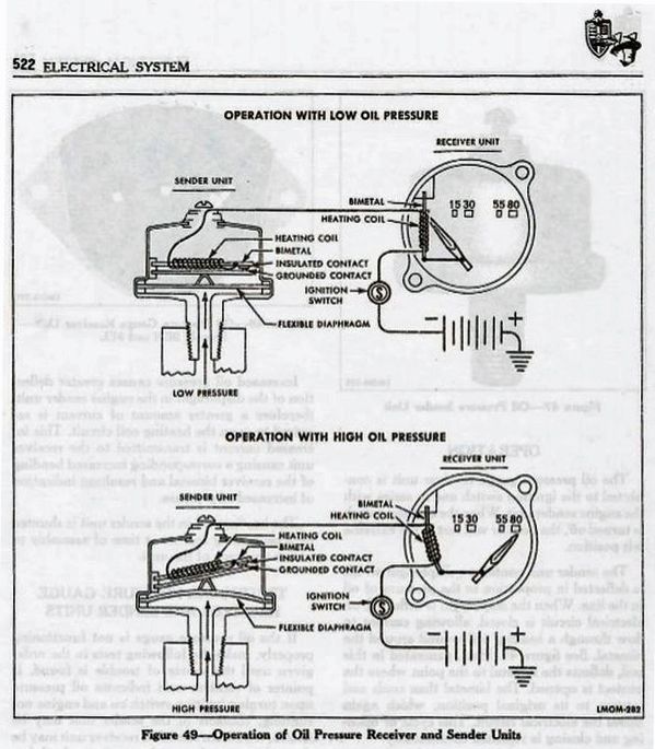 Temperature gauge: 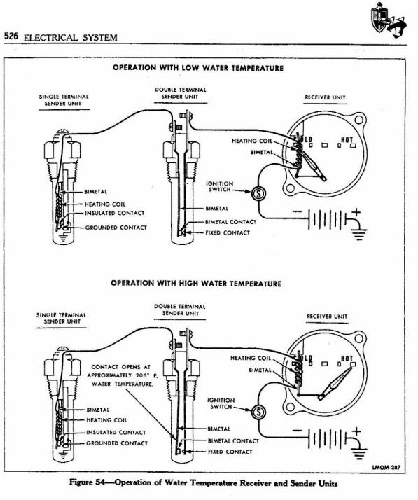 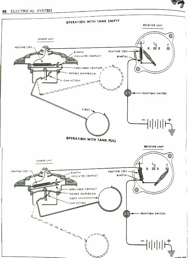
__________________
Prof. Henry (The Roaming Gnome)  "It is good to have an end to journey toward; but it is the journey that matters, in the end. *Ursula K. Le Guin in The Left Hand of Darkness Last edited by Old Henry; 04-06-2015 at 06:59 PM. |
|
|
|
|
04-06-2015, 04:51 PM
|
#5 |
|
Member Emeritus
Join Date: Nov 2012
Location: Wichita KS
Posts: 16,132
|
LOL Henry I just added the same ones! Well now we're sure the diagrams are in there!!! Yours are posted full size so guess that is an improvement.
|
|
|
|
|
04-06-2015, 05:00 PM
|
#6 | |
|
Senior Member
Join Date: Oct 2010
Location: Orem, Utah
Posts: 5,762
|
Sponsored Links (Register now to hide all advertisements)
Quote:
The new replacement gas senders are, in fact, resistance senders using a rheostat activated by the float.
__________________
Prof. Henry (The Roaming Gnome) "It is good to have an end to journey toward; but it is the journey that matters, in the end. *Ursula K. Le Guin in The Left Hand of Darkness |
|
|
|
|
|
04-06-2015, 05:04 PM
|
#7 |
|
Senior Member

Join Date: May 2010
Location: Coral Springs FL
Posts: 10,925
|
JSeery: Excellent. Thank you again.
I printed it all out. |
|
|
|
|
04-06-2015, 08:20 PM
|
#8 |
|
Senior Member

Join Date: Nov 2013
Location: Prescott, AZ
Posts: 585
|
Thanks for posting this info.
__________________
Nothing wrong with it except for the name on the front. Alex |
|
|
|
|
04-06-2015, 09:18 PM
|
#9 | |
|
Senior Member
Join Date: May 2010
Location: West Central Alberta
Posts: 441
|
Quote:
|
|
|
|
|
|
04-07-2015, 03:28 AM
|
#10 |
|
Senior Member

Join Date: May 2010
Location: Tehachapi, Ca.
Posts: 208
|
That same gauge system was used all the way up to 1985 save 1956. Then ford, in their infinite lack of wisdom went to the magnetic gauges like GM and we had trouble ever since. The gauges have no idea what they are reading and I have often taken a much later gauge with the same sweep, changed the needle and face from the older gauge and used it without problem. Ford Torinos and Ranchero Gt's from the '70's have donated their gauges for me on several occasions. The beauty and simplicity of a King-Seely gauge is incredible. Ford made a gauge tester that would fit to the sender wire and work for both 6 and 12 volt gauges, though only designed for 12 volt.One position checks the "IVR" but since the 6 volt doesn't need this function, the 6 volt gauge will respond to the test of low, middle, and high for gauge needle position. I used mine since the early '70's when I started in Ford dealerships and have it yet today squirrelled away in retirement. I guess I am a natural born pack rat.
|
|
|
|
|
04-07-2015, 07:51 AM
|
#11 |
|
Member
Join Date: May 2010
Location: south cent Ky
Posts: 70
|
If repo fuel senders are resistor type, what are the implications when installed with original fuel gauge? I have noticed that my fuel gauge (39 deluxe)takes several minutes to register correctly(not sure about accuracy) as does the volt meter.
|
|
|
|
|
04-07-2015, 08:29 AM
|
#12 | |
|
Senior Member
Join Date: Oct 2010
Location: Orem, Utah
Posts: 5,762
|
Quote:
__________________
Prof. Henry (The Roaming Gnome) "It is good to have an end to journey toward; but it is the journey that matters, in the end. *Ursula K. Le Guin in The Left Hand of Darkness |
|
|
|
|
|
04-07-2015, 08:36 AM
|
#13 |
|
Senior Member
Join Date: May 2010
Location: Coral Springs FL
Posts: 10,925
|
Old Henry, Who sells a modern gas guage sender that will accurately work with the original bi-metal Ford fuel gauge?
|
|
|
|
|
04-07-2015, 09:31 AM
|
#14 | |
|
Senior Member
Join Date: Oct 2010
Location: Orem, Utah
Posts: 5,762
|
Quote:
 Here's one at C&G: http://cgfordparts.com/ufolder/cgcat...&sp=Search+%23 Here's Bob Drake's: https://www.bobdrake.com/ItemForm.as...a-7f378a887934  I believe that's the one I bought and am using. Works fine.
__________________
Prof. Henry (The Roaming Gnome) "It is good to have an end to journey toward; but it is the journey that matters, in the end. *Ursula K. Le Guin in The Left Hand of Darkness Last edited by Old Henry; 04-07-2015 at 09:36 AM. |
|
|
|
|
|
04-07-2015, 11:47 AM
|
#15 |
|
Senior Member
Join Date: May 2010
Location: Coral Springs FL
Posts: 10,925
|
Thank you.
Not trying to beat a dead horse, BUT when you say, "I believe that's the one I bought and am using. Works fine." Did you buy the one from Mac's, C&G or Drake? Thanks again. |
|
|
|
|
04-07-2015, 11:49 AM
|
#16 | |
|
Senior Member
Join Date: Oct 2010
Location: Orem, Utah
Posts: 5,762
|
Quote:
__________________
Prof. Henry (The Roaming Gnome) "It is good to have an end to journey toward; but it is the journey that matters, in the end. *Ursula K. Le Guin in The Left Hand of Darkness |
|
|
|
|
|
04-07-2015, 11:57 AM
|
#17 |
|
Senior Member
Join Date: May 2010
Location: Coral Springs FL
Posts: 10,925
|
Thank you again. JIM
|
|
|
|
|
04-07-2015, 12:43 PM
|
#18 |
|
Senior Member

Join Date: Jun 2010
Location: San Antonio, Texas
Posts: 16,425
|
I've heard both sides of the coin on the rheostat variable resistance types. Most resistance based units use a specific Ohm resistance range and they vary between manufactures of the different units. Many claim that the repos work OK and then many claim they don't indicate accurate quantities. I think if you play with the adjustments you can gain some accuracy within a narrow band of meter movement but you can never get them to be accurate through out the range of movement. The resistance levels are more minute for working a current based indicator and the rheostats just can't attain the accuracy in those small levels of resistance change but they will give you some idea whether you are getting close to empty which is likely the most important use of a quantity indicating system. You may not know how much is left but that won't matter as much as the system causing you to run out of gas on the side of the road somewhere.
|
|
|
|
|
04-07-2015, 05:44 PM
|
#19 |
|
Senior Member

Join Date: May 2010
Location: Illinois
Posts: 2,183
|
JSeery, thank you for posting this.
John |
|
|
|
|
09-13-2016, 10:29 AM
|
#20 |
|
Senior Member

Join Date: Mar 2014
Location: Webster, NY
Posts: 215
|
I am afraid I am still a little dense troubleshooting the gas and temperature gauges. History: 1940 1-1/2 ton panel. I replaced the OEM gas sending unit with the one from Mac's. It gave readings that increased as I added gas to the tank using a 5-gallon can. Temperature gauge worked fine. Some time later I removed the distributor and spark plug wire assembly including looms to have the distributor serviced and new wires installed. I had to remove the temp sending wire (I have only a single one-terminal sending unit on the driver side) to get the driver side loom out. Ever since I reinstalled everything the temp gauge reads H and the gas gauge reads E. I checked the gas gauge by momentarily grounding a long jumper connected to the sending unit wire and the gauge read F. Both failures happened after I removed and reinstalled the temp sending unit wire. The temp sending wire has continuity to the gauge. Thoughts?
|
|
|
|
|
09-13-2016, 10:42 AM
|
#21 |
|
Member Emeritus
Join Date: Nov 2012
Location: Wichita KS
Posts: 16,132
|
Hard to say, did you mix the wiring up? Damage the sender? Because you are having two systems exhibit a problem I would guess a wiring problem. On the temperature gauge H indicates an open somewhere in the wiring or the sender.
|
|
|
|
|
09-13-2016, 01:13 PM
|
#22 |
|
Senior Member
Join Date: Mar 2014
Location: Webster, NY
Posts: 215
|
I did two things at the temp sending unit. I removed and reinstalled the wire to the sending unit. Only one wire and one place to reinstall it. I replaced the screw with a socket head cap screw because the original straight head screw was buggered. Both gauges stopped working properly afterward.
I will double check continuity of the wire and try the 1.5 volt battery test procedure on both gauges and look for mid-range. Key off, 6 volt input wires and sending unit wires disconnected from gauges? Operationally, with the temp sending unit wire disconnected, shouldn't the fuel gauge still work? Since the fuel gauge deflected full range with momentary contact by the jumper from the sending unit end of the wire, I assume (uhoh, there's that word) that the gauge has 6 volt supply and the wire from the sending unit has continuity. The ground wire at the fuel sending unit is good, but I will double check it for continuity with the positive cable on the battery disconnect. Last edited by FireEngineMike; 09-13-2016 at 01:20 PM. |
|
|
|
| Sponsored Links (Register now to hide all advertisements) |
|
|
|
07-04-2017, 10:49 AM
|
#23 | |
|
Senior Member

Join Date: Jan 2014
Location: Orcas Island Washington
Posts: 4,916
|
Quote:
__________________
Owner/Operator of 'Jailbar Ranch' on the side of Mt. Pickett. Current stable consists of 1946 1/2 ton pickup turned woodie wagon with FH V8, 1947 Tonner Pickup (red) mostly stock with exception of a cummins 6at turbo diesel, 1946 Tonner Pickup (green) with 226 cu in 6 cyl flathead, 1979 Toyota landcruiser wagon, completely encased in 1947 Ford Jailbar sheet metal. Ok, cornbinder rear fenders..... 'Rusty ol' floorboards, hot on their feet' (Alan Jackson) |
|
|
|
|
|
07-04-2017, 02:18 PM
|
#24 |
|
Member Emeritus
Join Date: Nov 2012
Location: Wichita KS
Posts: 16,132
|
The car use Positive ground and Negative for the power side. The gauge is wired with power from the ignition switch going to one terminal on the gauge and the other terminal connected to the sending unit. The negative side of the battery would connect to the ignition switch side of the gauge and the positive side would connect to the sender side of the gauge.
|
|
|
|
|
07-04-2017, 03:22 PM
|
#25 |
|
Senior Member

Join Date: Jul 2014
Location: Sharpsburg md
Posts: 480
|
Great information thanks
|
|
|
|
|
07-04-2017, 04:25 PM
|
#26 |
|
Senior Member
Join Date: Sep 2016
Posts: 628
|
Sponsored Links (Register now to hide all advertisements)
Not a resistance direct current system, the Ford gauge isn't an alternating current system either. Information really depends upon the on-off pulse ratio not the pulse rate. Sender open/pulses mostly off - gauge is at maximum. Sender pulses mostly on - gauge is minimum. Pulsing - gauge reads pulse off/on ratio. I do find it interesting how the similar temperature coefficient of both sender and gauge work to cancel each other resulting in a system quite accurate across a wide ambient range. . Last edited by Paul Bennett; 07-04-2017 at 06:22 PM. |
|
|
|
|
07-05-2017, 12:02 AM
|
#27 | |
|
Senior Member
Join Date: Jan 2014
Location: Orcas Island Washington
Posts: 4,916
|
Quote:
__________________
Owner/Operator of 'Jailbar Ranch' on the side of Mt. Pickett. Current stable consists of 1946 1/2 ton pickup turned woodie wagon with FH V8, 1947 Tonner Pickup (red) mostly stock with exception of a cummins 6at turbo diesel, 1946 Tonner Pickup (green) with 226 cu in 6 cyl flathead, 1979 Toyota landcruiser wagon, completely encased in 1947 Ford Jailbar sheet metal. Ok, cornbinder rear fenders..... 'Rusty ol' floorboards, hot on their feet' (Alan Jackson) |
|
|
|
|
|
07-05-2017, 07:13 AM
|
#28 |
|
Senior Member
Join Date: Oct 2016
Posts: 250
|
So does converting to 12V affect the accuracy of the gauge? I was always under the impression you only needed to drop the voltage at the gauge, but it seems from the diagram that both the gauge and the sending unit would be impacted by the 12V.
|
|
|
|
|
07-05-2017, 09:42 AM
|
#29 |
|
Member Emeritus
Join Date: Nov 2012
Location: Wichita KS
Posts: 16,132
|
All of the gauges work the same way, the current is from the gauge to the sender and to ground. A voltage drop is needed at the power input side of the gauge, the sender is just a path to ground. The circuit is matching the current flow through both the gauge and the sender. There is no way or reason you would attempt to connect a voltage drop device to the sender.
|
|
|
|
|
07-05-2017, 10:01 AM
|
#30 | |
|
Senior Member
Join Date: Jan 2014
Location: Orcas Island Washington
Posts: 4,916
|
Quote:
__________________
Owner/Operator of 'Jailbar Ranch' on the side of Mt. Pickett. Current stable consists of 1946 1/2 ton pickup turned woodie wagon with FH V8, 1947 Tonner Pickup (red) mostly stock with exception of a cummins 6at turbo diesel, 1946 Tonner Pickup (green) with 226 cu in 6 cyl flathead, 1979 Toyota landcruiser wagon, completely encased in 1947 Ford Jailbar sheet metal. Ok, cornbinder rear fenders..... 'Rusty ol' floorboards, hot on their feet' (Alan Jackson) |
|
|
|
|
|
07-05-2017, 11:30 AM
|
#31 |
|
Senior Member
Join Date: Jun 2010
Location: San Antonio, Texas
Posts: 16,425
|
Check out Randy Rundle's fifth avenue internet garage. He has about everything a person would need to switch to 12-volt. This includes dropping resistors & voltage regulators.
|
|
|
|
|
07-05-2017, 03:03 PM
|
#32 | |
|
Member Emeritus
Join Date: Nov 2012
Location: Wichita KS
Posts: 16,132
|
Quote:
|
|
|
|
|
|
07-05-2017, 06:11 PM
|
#33 |
|
Senior Member
Join Date: Jun 2010
Location: San Antonio, Texas
Posts: 16,425
|
The power in is at the gauge so it would need a runtz or a dropping resistor on there. The runtz units use one for each gauge I think but a dropping resistor or voltage regulator will drop all of them at once. Speedway carries this stuff too.
|
|
|
|
|
07-05-2017, 06:39 PM
|
#34 | |
|
Senior Member
Join Date: Oct 2016
Posts: 250
|
Quote:
|
|
|
|
|
|
07-05-2017, 07:40 PM
|
#35 |
|
Senior Member
Join Date: Jan 2014
Location: Orcas Island Washington
Posts: 4,916
|
So I looked at all Randy's stuff and he seems like a very knowledgeable straight shooter and I thank you. What has worked well over time, the speedway style that does all gauges or the runtz, needing three? Money seems about the same. I'm ready to pull the trigger on one way or the other.
__________________
Owner/Operator of 'Jailbar Ranch' on the side of Mt. Pickett. Current stable consists of 1946 1/2 ton pickup turned woodie wagon with FH V8, 1947 Tonner Pickup (red) mostly stock with exception of a cummins 6at turbo diesel, 1946 Tonner Pickup (green) with 226 cu in 6 cyl flathead, 1979 Toyota landcruiser wagon, completely encased in 1947 Ford Jailbar sheet metal. Ok, cornbinder rear fenders..... 'Rusty ol' floorboards, hot on their feet' (Alan Jackson) |
|
|
|
|
07-06-2017, 12:35 AM
|
#36 |
|
Senior Member

Join Date: Sep 2015
Location: Clarkdale, AZ
Posts: 121
|
I'd use the Runts units: one per gauge. Can't say for sure why, but I suspect the Runts may be more than a simple voltage dropping resitive load. In any event I like the idea of a single runtz unit responding to the individual load of each circuit rather than the average of the three parallel circuits.
|
|
|
|
|
07-06-2017, 08:42 AM
|
#37 |
|
Senior Member
Join Date: Jun 2010
Location: San Antonio, Texas
Posts: 16,425
|
The runtz is a mini regulator. It will keep accuracy better with separate units for each gauge.
|
|
|
|
|
07-06-2017, 09:18 AM
|
#38 |
|
Senior Member
Join Date: Jan 2014
Location: Orcas Island Washington
Posts: 4,916
|
Runtz it is! Thanks much.
__________________
Owner/Operator of 'Jailbar Ranch' on the side of Mt. Pickett. Current stable consists of 1946 1/2 ton pickup turned woodie wagon with FH V8, 1947 Tonner Pickup (red) mostly stock with exception of a cummins 6at turbo diesel, 1946 Tonner Pickup (green) with 226 cu in 6 cyl flathead, 1979 Toyota landcruiser wagon, completely encased in 1947 Ford Jailbar sheet metal. Ok, cornbinder rear fenders..... 'Rusty ol' floorboards, hot on their feet' (Alan Jackson) |
|
|
|
|
07-08-2017, 02:27 AM
|
#39 | |
|
Senior Member
Join Date: Apr 2015
Location: Sweden
Posts: 3,045
|
Quote:
Last conversion i did uses a switched stepdown converter and is now being under test for dependability. The stepdown converter modules are dirtcheap today i can´t buy a regulator and breadbord for what they sell online. If you use one for each gauge just about any dropping device including a simple resistor works fine. The gauge doesn´t care about the voltage...you just need to limit the current rush a bit. |
|
|
|
|
|
07-08-2017, 08:15 AM
|
#40 |
|
Senior Member
Join Date: Jun 2010
Location: San Antonio, Texas
Posts: 16,425
|
The sender is not the problem so much as it is the generator output. It fluctuates even more on a generator than on an alternator but a change to 12-volts with an alternator changes things a lot. Fluctuation can be anything from 6-volts to 7.1 volts with the original set up but with 12-volts it's a different story (much more voltage spread at 12 to 14.7) and those little runtz regulators will keep it the same all the time and each gauge will be regulated separately so there are less chances of spikes creating any problems.
The gauges do care about voltage and especially amperage. Add twice the voltage to the mix also adds twice the amount of higher spike capability. Ford used constant voltage regulators on these systems for a long time after the change to 12-volt and for good reason. The runtz is a step down switching converter or regulator if you choose. A person can build one cheaper but the labor involved along with soldering skills makes the runtz a relatively inexpensive way to do things. Definitely less hassle unless a person just likes to do that stuff themselves. A person could make 4 of them for the price of one prefabricated one if they were so inclined. Last edited by rotorwrench; 07-08-2017 at 08:33 AM. |
|
|
|
|
07-08-2017, 09:39 AM
|
#41 |
|
Senior Member

Join Date: May 2010
Location: Highland,MI
Posts: 1,196
|
Thanks JSeery for the great info...Ken
|
|
|
|
|
07-08-2017, 01:32 PM
|
#42 |
|
Senior Member
Join Date: Apr 2015
Location: Sweden
Posts: 3,045
|
The gauges don´t care about voltage !!
What you need to keep down is the current rush (amperage). If you let the current rush freely the gauge will be jumping around keeping it low will give you a slower movement. So the voltage drop will give you less current flow since resitance in the circuit is constant. A step down converter ready built is starting at about $1 today...you want them to deliver over 3-4amps they start to get expensive. |
|
|
|
| Sponsored Links (Register now to hide all advertisements) |
|
|
|
07-08-2017, 06:52 PM
|
#43 | |
|
Senior Member

Join Date: May 2010
Location: 74FL
Posts: 323
|
Quote:
And all I can add is if you've got a 1940 Car/Truck with a BATT gauge instead of an Ammeter, all it does is replace the sending unit with a 60ohm resistance built-in. Therefore, when converting to 12V, adding another 60ohm resistor in series with the gauge will produce a pretty good 12V BATT gauge.
__________________
Daddy always said, "If yer gonna be dumb, you gotta be tough" and I'm one tough sumbitch! T5 Tech |
|
|
|
|
|
07-08-2017, 07:29 PM
|
#44 |
|
Member
Join Date: Apr 2013
Location: Auburn, CA
Posts: 86
|
Thanks for this valuable information.
|
|
|
|
|
07-09-2017, 12:50 AM
|
#45 | |
|
Senior Member
Join Date: Apr 2015
Location: Sweden
Posts: 3,045
|
Quote:
Since the sender is wirewound it will go in steps changing from one wire to another and with a low ohm range each step will make a bigger change in the reading. And the sender can´t be linear in it´s winding or only empty and full reading will be accurate. This is one the reason modern instruments went to higher ranges like 120/240 ohm. |
|
|
|
|
|
07-09-2017, 08:41 AM
|
#46 |
|
Senior Member
Join Date: Jun 2010
Location: San Antonio, Texas
Posts: 16,425
|
Sponsored Links (Register now to hide all advertisements)
King Seeley units were more of a variable amperage device with the device on the other end mirroring it's position. Since it uses temperature sensitive bimetallic switches, it could be easily adapted for both temperature and pressure sensitive reading devices. On the fuel quantity it was a pressure sensitive device with the float arm providing different pressures depending on the level in the tank. A very simple but ingenious device. Ohmic type rheostats start wearing out the second you start to rub the brush on the wire wound resistor. It's just a matter of time before the brush wears down or the wire wears through making an open circuit. The more wear they have the less reliable they become due to wear and crud build up. |
|
|
|
|
07-09-2017, 05:20 PM
|
#47 | |||
|
Senior Member
Join Date: May 2010
Location: 74FL
Posts: 323
|
Quote:
That said, I only replace the original senders if they're broken and I can't find another...but it's nice to know the aftermarket senders can be made to work reasonably well. Quote:
Quote:
Something else no one has addressed is the adjustment of the early gauges - on most of these gauges, there is an adjustment to change the bias of the bimetallic spring to add or reduce the at-rest tension.
__________________
Daddy always said, "If yer gonna be dumb, you gotta be tough" and I'm one tough sumbitch! T5 Tech |
|||
|
|
|
|
07-09-2017, 07:25 PM
|
#48 |
|
Senior Member
Join Date: Sep 2016
Posts: 628
|
All this "technically correct' is NOT technically correct. Ammeters do NOT measure flow but measure voltage across a fixed resistance calibrated (or not) in Amps using a d'Arsenval movement.
Ford applications of 'Gas Level' 'Oil Pressure' and 'Temperature' do NOT use d'Arsenval movement gauges but THERMOSTATIC gauge which, as JSeary has tried to point out, is different. Resistance senders were considered hazardous early on because the armature must transition from one coil to the next. So Ted Smulski invented and patented the thermostatic gauge system, which is odd considering the sender must open and close a set of terminals in the flammable fluid. Ted's patent used the term 'thermostatic gauge' - it was assigned to Anderson Corp who contracted King-Seeley to manufacture gauges/senders. The patent claims was compact, convenient, duragle and not sensitive to voltage. Senders - resistance vs thermostatic. Actually, were a d'Arsonval meter be used with a thermostatic sender, the gauge would pulse hi-lo-hi-lo but a thermostatic meter evens out the peaks and presents a true ratio of on-off periods. Ironically, a year after the Smulski patent, Joe Zublaty was granted a patent on a resistance gauge because the flamability nature of gasoline was found not a danger with a resistance sender. A galvanometer or ohm meter was used for the readout. King-Seeley filed for a resistance gauge patent in 1954 obviously with knowlege of Ford's conversion to 12v. I've heard Ford switched to resitance fuel gauge in 1955 for one year switching back until 1980 but can't confirm it. |
|
|
|
|
07-09-2017, 07:37 PM
|
#49 |
|
Senior Member
Join Date: Sep 2016
Posts: 628
|
It would seem most posters have their own way of thinking how electricity works and how gauges fit into the equation. I could quibble but won't. What it boils down to is interesting and I do hope JSeary is able to recover from his seemingly futile attempt to educate the troops but not so futile, really.
Ford gauges boil down to politics and economics to which we are not privy. Some of the history we do know. Ford applications of 'Gas Level' 'Oil Pressure' and 'Temperature' do NOT use d'Arsenval movement gauges but THERMOSTATIC gauge which, as JSeary has tried to point out, is different. This undoubtly stems from: Resistance senders were considered hazardous early on because the armature must transition from one coil to the next. So Ted Smulski invented and patented the thermostatic gauge system, which is odd considering the sender must open and close a set of terminals in the flammable fluid. Ted's patent used the term 'thermostatic gauge' - it was assigned to Anderson Corp who contracted King-Seeley to manufacture gauges/senders. The patent claims was 'compact, convenient, duragle and not sensitive to voltage'. The Oil Pressure and Temperature gauge applications tagged along soon afterwards. Ironically, a year after the Smulski patent, Joe Zublaty was granted a patent on a resistance gauge because the flamability nature of gasoline was found not a danger with a resistance sender. A galvanometer or ohm meter was used for the readout. King-Seeley filed for a resistance gauge patent in 1954 obviously with knowlege of Ford's conversion to 12v. I've heard Ford switched to resitance fuel gauge in 1955 for one year switching back until 1980 but can't confirm it. . |
|
|
|
|
07-14-2017, 11:21 AM
|
#50 | |
|
Senior Member
Join Date: May 2010
Location: 74FL
Posts: 323
|
Quote:
From a practical perspective, all gauges are measuring current flow in a closed circuit between the sender and the gauge - there is no other way to measure anything electrically (leaving capacitance type gauges out of the equation because they're generally not used in automotive applications). In a 'modern' resistance type set up, a gas gauge float moves an arm on a potentiometer which changes resistance, which, in turn, changes the total current flowing through the gauge. The gauge is reading this change in current...therefore, it is an ammeter insofar as it is reacting (measuring) the total current in the circuit. It just happens to be calibrated to show you how much resistance = full/half/empty. The same is true of the heated bimetallic strip bending and making/breaking a set of contact points. It opens/closes allowing intermittent full current to go through the gauge circuit...which has its own bimetallic arm moving a gear train and then a needle...it is reacting to the average current flowing through it...and it's an ammeter calibrated to reflect oil/gas/temp. There is more than one way to measure total current in any circuit. At the end of the day, the electrical theorists (myself included) do those with a little less electrical knowledge a great disservice by complicating things that don't need to be complicated...
__________________
Daddy always said, "If yer gonna be dumb, you gotta be tough" and I'm one tough sumbitch! T5 Tech |
|
|
|
|
|
07-14-2017, 01:03 PM
|
#51 |
|
Senior Member
Join Date: Jun 2010
Location: San Antonio, Texas
Posts: 16,425
|
Voltage and amperes work hand in hand. Voltage is the electromotive force that allows for flow and amperes are the electrical force that flows. The variable resistor or rheostat is a variable load device. The voltage is altered by the change in electrical load so it also changes how much amperage can flow. Ohms law is used to calculate the variables between the two. If there is no load in circuit (from the rheostat) then there is less resistance to flow but the voltage is still 6 to 7-volts. As the load increases, the resistance to flow increases. This is what the meter reads. You can call it an ammeter or a voltmeter but one is a bit more accurate than the other.
|
|
|
|
|
07-14-2017, 04:59 PM
|
#52 | |
|
Senior Member
Join Date: Sep 2016
Posts: 628
|
Quote:
|
|
|
|
|
|
07-14-2017, 06:43 PM
|
#53 |
|
Senior Member

Join Date: May 2010
Location: NorCal
Posts: 2,617
|
On my 39 Ford coupe, when I converted to 12 volts, all I did was add resisters to two of the three gauges. Everything worked fine. Temperature was not considered, as it was mechanical.
JSeery Thanks so much for your very informative posts. I appreciate them all Jim |
|
|
|
|
11-13-2017, 07:44 AM
|
#54 |
|
Junior Member

Join Date: Jun 2017
Location: Central Michigan
Posts: 17
|
This is a great thread, Thanks to all of you who contributed. You guys seem to be at the electrical engineer level. Way over my head but has explained alot. I have a f100 that is a hodge podge of a 55 and 56. It uses the 55 tank and the 56 speedo head/gauges ( long story) Anyway I will be dealing with the gas gauge later. You can imagine the problems I have ran into with the voltage change between 55 and 56, and the 56 only heater/ defroster assembly. I will be studying out this thread when I get to that point. Thanks again, Greg
|
|
|
|
|
11-13-2017, 08:03 AM
|
#55 |
|
Member Emeritus
Join Date: Nov 2012
Location: Wichita KS
Posts: 16,132
|
Remember that when Ford switched to 12v the gauges remained 6v. Ford used a voltage reducer for the gauges.
|
|
|
|
|
11-13-2017, 09:44 AM
|
#56 |
|
Senior Member
Join Date: May 2010
Location: Coral Springs FL
Posts: 10,925
|
Years ago I followed FlatErnie's advice and used a CVR to convert to 12V. Also isolated the 40 BATT gauge and used a 60 ohm resistor. Still working fine. Read all about what to do and how to do it here:
https://www.fordbarn.com/forum/showt...ert+gauges+12v |
|
|
|
|
02-20-2020, 05:48 PM
|
#57 |
|
Member

Join Date: Oct 2018
Location: Austin, Texas
Posts: 39
|
Very helpful!!! Thanks
|
|
|
|
|
02-20-2020, 10:56 PM
|
#58 |
|
Senior Member

Join Date: Apr 2017
Location: Texas Gulf Coast
Posts: 727
|
I just have a simple question, my gauge reads full when tank is full but when it reads about E I only have room for 10 gal. in a 17 gal. tank. Do I need to bend the float arm down or shorten it. Al
|
|
|
|
|
02-21-2020, 05:41 AM
|
#59 |
|
Senior Member

Join Date: May 2010
Location: Masterton, New Zealand
Posts: 3,829
|
And I have a question too - sorry!
Running 36 fuel tank, original sender, original dash unit, 12 volt conversion, [alternator], runtz on gas gauge, another on oil pressure gauge. Problem is that upon turning on ignition, needle in fuel gauge will climb and indicate [approximate] fuel level, but then when I start the engine and start driving, the needle goes down below empty and stays there. Why would this be?
__________________
Unfortunately, two half wits don't make a whole wit! |
|
|
|
|
02-21-2020, 09:41 AM
|
#60 | |
|
Senior Member

Join Date: Dec 2011
Location: Oakville Ontario
Posts: 586
|
Quote:
|
|
|
|
|
|
02-21-2020, 12:35 PM
|
#61 | |
|
Member Emeritus
Join Date: Nov 2012
Location: Wichita KS
Posts: 16,132
|
Quote:
|
|
|
|
|
|
02-21-2020, 12:39 PM
|
#62 | |
|
Member Emeritus
Join Date: Nov 2012
Location: Wichita KS
Posts: 16,132
|
Quote:
Assuming the tank is indeed full and reads full with the ignition switch on, the gauge would be indicating maximum current flow through the gauge and sending unit (or some source to ground). If it drops when the engine starts something is reducing the current flow, as in an open circuit or grounding issue. Is there something somewhere that could move/change when the engine is running? I would trouble shoot starting at the gauge. Connect a jumper wire to the sender post on the gauge. Once the engine is running and the gauge starts to move toward empty touch the jumper to a known good ground and see it the gauge starts to return to full (I would do this for only a short period of time). If it does the problem is not the gauge. I would next connect a jumper to the sender unit connection (at the sender unit) and try it again. If the gauge stays on empty there may be a wiring problem between the gauge and the sender. If it moves back toward full in may be the sender itself or a ground issue. To check between the sender being the issue and a poor ground, connect a jumper to a mounting bolt for the sender and try again. If the gauge stays on empty I would suspect the sender itself if it goes back to full it is most likely a sender grounding issue. Last edited by JSeery; 02-21-2020 at 02:13 PM. |
|
|
|
|
| Sponsored Links (Register now to hide all advertisements) |
|
|
|
07-02-2023, 02:48 AM
|
#63 | |
|
Member

Join Date: Oct 2012
Location: Tasmania Australia. The land of the REAL Tasmanian Devil
Posts: 46
|
Quote:
I know I'm resurrecting a 3 year old post here, but I'm wondering if Brian ever sorted out his fuel gauge problem where it would start reading ok then dropping back to zero - because I'm having somewhat of a similar problem, but I'm pretty sure I know what's causing mine. I found the points in the sender unit pitted and dirty, so I disassembled the thing, - yeah, you can disassemble the things if you're careful ! -and filed the points flat to get rid of the pitting, (used wifey's nail file  ) got them all clean, sprayed them with electrical contact cleaner, reassembled it, adjusted the little toothed adjusting wheel to get a reasonably accurate reading at the gauge and put it back in the tank. ) got them all clean, sprayed them with electrical contact cleaner, reassembled it, adjusted the little toothed adjusting wheel to get a reasonably accurate reading at the gauge and put it back in the tank. All was good for half an hour then the needle decided to start wandering before dropping down to empty. So I pulled the sender back out, cleaned and sprayed the points again, reinstalled it and same thing, except this time it lasted a little longer. So I've tried this 3 or 4 times now and it keeps happening. If I tap the top of the sender unit while it's in the tank it comes good - (shitty points!?) I've dissembled the sender unit a couple of times now and I'm happy that everything else is good. Earths out ok. I've earthed the tank to the chassis so I'm not relying on the tank holding straps for my earth to to sender unit. Somewhere in the dim dark past in the back of my mind I seem to remember something about points (well, ignition points anyway) might have been "coated" to help against pitting, or going resistive. Is that true? Perhaps I've taken that coating off by filing them ? Wiring's all new and good. I rebuilt and rewired the car. And I'm using a single LM7806 IC heatsinked to the steel dash cluster to drop 12v down to 6v. They're not rated to draw 2 amps, (which is what I measured when the contacts were closed) but the IC's not getting hot, the oil and water gauges are reading ok and I'm measuring 6volts at the ign side of the gauge. So there ya go folks. What the bloody hell's going on here? Your thoughts ? Mick (In real Tasmanian Devil country) |
|
|
|
|
|
07-02-2023, 11:16 AM
|
#64 |
|
Senior Member
Join Date: Jun 2010
Location: San Antonio, Texas
Posts: 16,425
|
Intermittent function is generally caused by an intermittent connection somewhere in the system. If tapping on the sender affects it then it's in there somewhere. It may not be getting a good ground. The ground path is fairly long on a fuel tank back to the frame. The power comes from the battery and passes through both the heating coil in the indicator unit and the heating coil in the sender so it's a pretty long circuit since it runs near the length of the car.
Our dear friend J Seery passed a while back so be aware that old threads are not always the best way to get the help you seek. Don't hesitate to start a new thread. Welcome into the Ford barn. |
|
|
|
|
07-02-2023, 02:45 PM
|
#65 |
|
Senior Member
Join Date: May 2010
Location: Masterton, New Zealand
Posts: 3,829
|
Yes, I did sort out the problem....I tried another sender unit, but it too had some sort of issue, I can't remember. Then, I found in my stash, yet another sender, a dirty, rusty looking thing, dunno where I got it from. Fitted it and, sweet! I works spot on.
Sorry I can't offer advice as to what was wrong with the original sender unit, I haven't needed to investigate further...if it ain't broke, don't fix it!! If you can find another sender unit, try it, may just work....good luck.
__________________
Unfortunately, two half wits don't make a whole wit! |
|
|
|
|
07-02-2023, 06:47 PM
|
#66 |
|
Member
Join Date: Oct 2012
Location: Tasmania Australia. The land of the REAL Tasmanian Devil
Posts: 46
|
Sponsored Links (Register now to hide all advertisements)
Sad to hear of the passing of Mr Seery. From what I've gleaned reading over the forum here, he appeared to be a pretty knowledgeable guy. We've lost a couple of good guys in the club of which I'm a member, over the last four years or so. Always sad. It's probably the same stateside with you guys, but I've noticed that most of us in the Classics & hot rod fraternity are well beyond the age of wisdom teeth ! Well, I'll persist with my fuel gauge issue over a time and when i sort it out I'll stick it up here on the forum as it may be of benefit to others. Mick |
|
|
|
|
01-24-2024, 06:07 AM
|
#67 |
|
Member
Join Date: Oct 2012
Location: Tasmania Australia. The land of the REAL Tasmanian Devil
Posts: 46
|
Very belated update on the intermittent fuel sender problem. I ended up pulling the unit back out. Disassembled it on the bench and aggressively filed the points till the pitting was almost gone. Then put it back together. I had to very slightly adjust the tooted adjuster to get the gauge accuracy back, but, touch wood, it's been good ever since.
__________________
Grandfathers.... 'cause we know stuff and fix things |
|
|
|
|
01-25-2024, 11:58 AM
|
#68 |
|
Senior Member

Join Date: Oct 2011
Location: Shelton, WA
Posts: 3,799
|
It is the FREQUENCY of the opening and closing of the points in the sender that is being measured by the gauge end which is calibrated to the sender. In a word, the gauge is measuring FREQUENCY. This is true of all the King Seeley systems, same for the temperature gauge as the gas gauge. It is not a voltage or resistance measurement at the gauge end.
|
|
|
|
|
01-25-2024, 05:09 PM
|
#69 | |
|
Member
Join Date: Oct 2012
Location: Tasmania Australia. The land of the REAL Tasmanian Devil
Posts: 46
|
Quote:
Bad typo there. Try ..."toothed adjuster". You know the little thing I mean in the sender unit. You adjust the mechanical pressure on the points so that they will break easier or not.
__________________
Grandfathers.... 'cause we know stuff and fix things |
|
|
|
|
|
«
Previous Thread
|
Next Thread
»
 Linear Mode

|
|

| Sponsored Links (Register now to hide all advertisements) |
|
|
All times are GMT -5. The time now is 04:33 PM.