|
|||||||


| Sponsored Links (Register now to hide all advertisements) |
|
|
 |

|
Thread Tools | Display Modes |
 04-06-2015, 03:05 PM
|
#1 |
|
Member Emeritus
Join Date: Nov 2012
Location: Wichita KS
Posts: 16,132
|
Based on several resent post there seems to be a lot of confusion about how early Ford gauges work. They are NOT resistant units and are unique to Ford as far a I know. A lot of the following is directly lifted from a Ford Shop Manuel. There are also a lot of older post on the Barn on this same issue.
The 6v Ford gauges (Fuel Level, Oil Pressure & Temperature) all work on similar principles. They have two major components, a Sender Unit and a Gauge Unit. The senders use a bimetal element and a heating coil to control the average current flow through both units. The Gauge Unit pointer is controlled by another bimetal and heating coil unit. When the ignition switch is on, current flows through the circuit and warms the Sending Unit bimetal by means of a heating coil, causing the bimetal strip to bend and open a set of contact points. When the points open the current is interrupted allowing the bimetal to cool and close the contact points again. This cycle then repeats and the points vibrate open and closed pulsing the current in the circuit. Because the current through the heating coil in the Sending Unit also flows through the heating coil in the Gauge Unit, the amount of heat supplied to the gauge unit is about the same as the heat in the Sending Unit. The amount of heat in both units is controlled by the average current flowing through the circuit due to the repeated opening and closing of the contact points. The Sending Unit varies the current required to open and close the contact points by varying the pressure on the bimetal strip making it harder or easier for the points to open and close. The more pressure on the points the more heat (current) that is required to open the points. Likewise, the less the pressure on the points the less heat (current) that is required. The different gauges use slightly different mechanical systems to accomplish this. Fuel Level Sender Unit:When the tank is filled, the float rises with the fuel level in the tank and a cam moves the ground contact toward the bimetal arm, increasing the tension holding the contacts closed. A greater amount of current is required to heat the Sending Unit bimetal arm enough to cause it to open the contacts. A similar greater bending of the bimetal arm occurs in the Gauge Unit and results in a movement of the needle toward the full position on the scale. Oil Pressure Sender Unit: When there is no oil pressure, the contact points are just touching and the gauge pointer register at the 0 position. Any increase in oil pressure bends a diaphragm, which in turn increases the tension on the bimetal arm. More heat must be supplied to cause the contacts to open and a resulting increase in the average current flow to supply this heat. This increase in average current flow in the circuit heats the coil in the Gauge Unit which bends the bimetal strip and moves the pointer. Temperature Sender Unit(s): The Temperature Sender is coupled with a Thermal switch. When the engine is cool the bimetal arm in the Sending Unit has maximum tension holding the contacts closed. The Maximum average current is necessary to open the contacts. The heating effect of the current causes the Gauge Unit bimetal arm and pointer to defect toward the C position of the scale. As the engine temperature increases, less current is required to keep the contacts at the break point since the increase in engine temperature causes the Sending Unit bimetal to bend away from the grounded contact. The Gauge Unit pointer then registers toward the H position of the scale. The Sending Unit has one electric terminal. The Thermal Switch can be identified by the two terminal connectors on it. The switch is set to open at 200-212° F. With a sending unit in one cylinder bank and the switch in the other cylinder bank, the Gauge Unit will indicate a boiling condition in either bank. Testing a Gauge System Fuel Level & Oil Pressure System Tests: Gauge Unit can be tested by disconnecting the wiring to the Gauge Unit and connecting it to a 1 ½ volt source (a D cell battery works well). The gauge should display mid-scale with a 1 ½ volt input and full-scale with 3 volt input (two D cell batteries). The suggested test of a Sending Unit is to test it by substituting a know good gauge to see if it will read correctly with the suspect Sending Unit. If it does not work correctly with a know good gauge the problem could be a bad Sender Unit or a bad connection between the Sender Unit and the Gauge Unit. Oil Pressure System Test: The gauge test is the same as for the Fuel Level and Oil Pressure Gauge Unit test. The Sending Unit is checked the same as the Fuel Level and Oil Pressure Sending Unit. The Thermal Switch can be tested to see if it is closed at normal temperatures. It can be tested with a test light or an ohm meter. It should show continuity. The switch can then be tested to determine if it opens at boiling temperature by placing the bulb in boiling water and testing it. At temperature it show test as an open. Edit: on another post it was pointed out that by shorting the electrical terminal on the sending unit you are causing full current to flow through the Gauge Unit which would move the pointer on the gauge to full scale. I would be very carful doing this test because it would be easy to damage the heater coil in the Gauge Unit. It should be a momentary test. If the Gauge Unit responds then the Sending Unit may be the problem. If not it could be the wire between the two or the Gauge Unit itself. I would lean toward the "D" cell battery test, much easier on the Gauge Unit. Last edited by JSeery; 04-06-2015 at 04:50 PM. |

|

|
|
04-06-2015, 04:06 PM
|
#2 |
|
Senior Member

Join Date: Mar 2014
Location: Jacksonville FL
Posts: 3,946
|
How far does this process go?? All the way through 1953??
|
|
|
|
| Sponsored Links (Register now to hide all advertisements) |
|
|
|
04-06-2015, 04:09 PM
|
#3 | |
|
Member Emeritus
Join Date: Nov 2012
Location: Wichita KS
Posts: 16,132
|
Quote:
|
|
|
|
|

|
04-06-2015, 04:43 PM
|
#4 |
|
Senior Member

Join Date: Oct 2010
Location: Orem, Utah
Posts: 5,762
|
That's great info. I'll just add two diagrams that I have to illustrate the text.
Oil pressure gauge system: 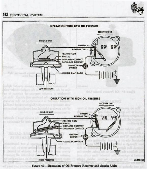 Temperature gauge: 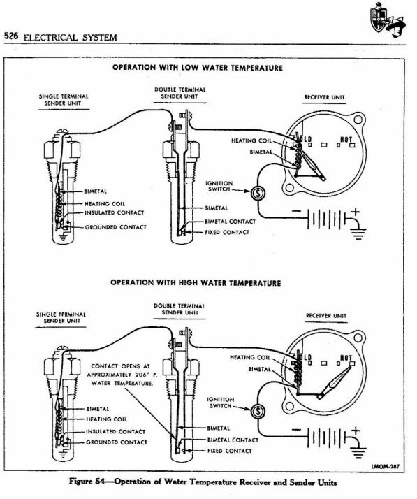 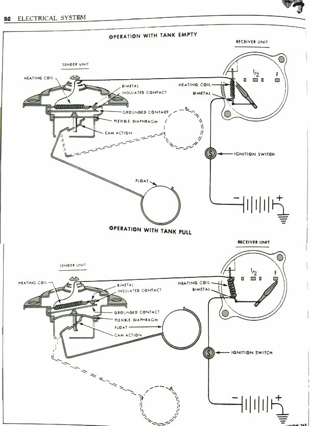
__________________
Prof. Henry (The Roaming Gnome)  "It is good to have an end to journey toward; but it is the journey that matters, in the end. *Ursula K. Le Guin in The Left Hand of Darkness Last edited by Old Henry; 04-06-2015 at 06:59 PM. |
|
|
|
|
04-06-2015, 04:51 PM
|
#5 |
|
Member Emeritus
Join Date: Nov 2012
Location: Wichita KS
Posts: 16,132
|
LOL Henry I just added the same ones! Well now we're sure the diagrams are in there!!! Yours are posted full size so guess that is an improvement.
|
|
|
|
|
04-06-2015, 05:00 PM
|
#6 | |
|
Senior Member
Join Date: Oct 2010
Location: Orem, Utah
Posts: 5,762
|
Sponsored Links (Register now to hide all advertisements)
Quote:
The new replacement gas senders are, in fact, resistance senders using a rheostat activated by the float.
__________________
Prof. Henry (The Roaming Gnome) "It is good to have an end to journey toward; but it is the journey that matters, in the end. *Ursula K. Le Guin in The Left Hand of Darkness |
|
|
|
|
|
04-06-2015, 05:04 PM
|
#7 |
|
Senior Member

Join Date: May 2010
Location: Coral Springs FL
Posts: 10,919
|
JSeery: Excellent. Thank you again.
I printed it all out. |
|
|
|
|
04-06-2015, 08:20 PM
|
#8 |
|
Senior Member

Join Date: Nov 2013
Location: Prescott, AZ
Posts: 585
|
Thanks for posting this info.
__________________
Nothing wrong with it except for the name on the front. Alex |
|
|
|
|
04-06-2015, 09:18 PM
|
#9 | |
|
Senior Member
Join Date: May 2010
Location: West Central Alberta
Posts: 441
|
Quote:
|
|
|
|
|
|
04-07-2015, 03:28 AM
|
#10 |
|
Senior Member

Join Date: May 2010
Location: Tehachapi, Ca.
Posts: 208
|
That same gauge system was used all the way up to 1985 save 1956. Then ford, in their infinite lack of wisdom went to the magnetic gauges like GM and we had trouble ever since. The gauges have no idea what they are reading and I have often taken a much later gauge with the same sweep, changed the needle and face from the older gauge and used it without problem. Ford Torinos and Ranchero Gt's from the '70's have donated their gauges for me on several occasions. The beauty and simplicity of a King-Seely gauge is incredible. Ford made a gauge tester that would fit to the sender wire and work for both 6 and 12 volt gauges, though only designed for 12 volt.One position checks the "IVR" but since the 6 volt doesn't need this function, the 6 volt gauge will respond to the test of low, middle, and high for gauge needle position. I used mine since the early '70's when I started in Ford dealerships and have it yet today squirrelled away in retirement. I guess I am a natural born pack rat.
|
|
|
|
|
04-07-2015, 07:51 AM
|
#11 |
|
Member
Join Date: May 2010
Location: south cent Ky
Posts: 70
|
If repo fuel senders are resistor type, what are the implications when installed with original fuel gauge? I have noticed that my fuel gauge (39 deluxe)takes several minutes to register correctly(not sure about accuracy) as does the volt meter.
|
|
|
|
|
04-07-2015, 08:29 AM
|
#12 | |
|
Senior Member
Join Date: Oct 2010
Location: Orem, Utah
Posts: 5,762
|
Quote:
__________________
Prof. Henry (The Roaming Gnome) "It is good to have an end to journey toward; but it is the journey that matters, in the end. *Ursula K. Le Guin in The Left Hand of Darkness |
|
|
|
|
|
04-07-2015, 08:36 AM
|
#13 |
|
Senior Member
Join Date: May 2010
Location: Coral Springs FL
Posts: 10,919
|
Old Henry, Who sells a modern gas guage sender that will accurately work with the original bi-metal Ford fuel gauge?
|
|
|
|
|
04-07-2015, 09:31 AM
|
#14 | |
|
Senior Member
Join Date: Oct 2010
Location: Orem, Utah
Posts: 5,762
|
Quote:
 Here's one at C&G: http://cgfordparts.com/ufolder/cgcat...&sp=Search+%23 Here's Bob Drake's: https://www.bobdrake.com/ItemForm.as...a-7f378a887934  I believe that's the one I bought and am using. Works fine.
__________________
Prof. Henry (The Roaming Gnome) "It is good to have an end to journey toward; but it is the journey that matters, in the end. *Ursula K. Le Guin in The Left Hand of Darkness Last edited by Old Henry; 04-07-2015 at 09:36 AM. |
|
|
|
|
|
04-07-2015, 11:47 AM
|
#15 |
|
Senior Member
Join Date: May 2010
Location: Coral Springs FL
Posts: 10,919
|
Thank you.
Not trying to beat a dead horse, BUT when you say, "I believe that's the one I bought and am using. Works fine." Did you buy the one from Mac's, C&G or Drake? Thanks again. |
|
|
|
|
04-07-2015, 11:49 AM
|
#16 | |
|
Senior Member
Join Date: Oct 2010
Location: Orem, Utah
Posts: 5,762
|
Quote:
__________________
Prof. Henry (The Roaming Gnome) "It is good to have an end to journey toward; but it is the journey that matters, in the end. *Ursula K. Le Guin in The Left Hand of Darkness |
|
|
|
|
|
04-07-2015, 11:57 AM
|
#17 |
|
Senior Member
Join Date: May 2010
Location: Coral Springs FL
Posts: 10,919
|
Thank you again. JIM
|
|
|
|
|
04-07-2015, 12:43 PM
|
#18 |
|
Senior Member

Join Date: Jun 2010
Location: San Antonio, Texas
Posts: 16,420
|
I've heard both sides of the coin on the rheostat variable resistance types. Most resistance based units use a specific Ohm resistance range and they vary between manufactures of the different units. Many claim that the repos work OK and then many claim they don't indicate accurate quantities. I think if you play with the adjustments you can gain some accuracy within a narrow band of meter movement but you can never get them to be accurate through out the range of movement. The resistance levels are more minute for working a current based indicator and the rheostats just can't attain the accuracy in those small levels of resistance change but they will give you some idea whether you are getting close to empty which is likely the most important use of a quantity indicating system. You may not know how much is left but that won't matter as much as the system causing you to run out of gas on the side of the road somewhere.
|
|
|
|
|
04-07-2015, 05:44 PM
|
#19 |
|
Senior Member

Join Date: May 2010
Location: Illinois
Posts: 2,183
|
JSeery, thank you for posting this.
John |
|
|
|
|
09-13-2016, 10:29 AM
|
#20 |
|
Senior Member

Join Date: Mar 2014
Location: Webster, NY
Posts: 215
|
I am afraid I am still a little dense troubleshooting the gas and temperature gauges. History: 1940 1-1/2 ton panel. I replaced the OEM gas sending unit with the one from Mac's. It gave readings that increased as I added gas to the tank using a 5-gallon can. Temperature gauge worked fine. Some time later I removed the distributor and spark plug wire assembly including looms to have the distributor serviced and new wires installed. I had to remove the temp sending wire (I have only a single one-terminal sending unit on the driver side) to get the driver side loom out. Ever since I reinstalled everything the temp gauge reads H and the gas gauge reads E. I checked the gas gauge by momentarily grounding a long jumper connected to the sending unit wire and the gauge read F. Both failures happened after I removed and reinstalled the temp sending unit wire. The temp sending wire has continuity to the gauge. Thoughts?
|
|
|
|
|
«
Previous Thread
|
Next Thread
»
| Thread Tools | |
| Display Modes | |


 Linear Mode

|
|

| Sponsored Links (Register now to hide all advertisements) |
|
|
All times are GMT -5. The time now is 10:23 AM.